Isuzu Rodeo UE. Manual — part 245

6E1–351
RODEO X22SE 2.2L ENGINE DRIVEABILITY AND EMISSION
DTC P1635 5 Volt Reference Voltage Circuit Malfunction
Step
Action
Value(s)
Yes
No
1
Was the ”On–Board Diagnostic (OBD) System Check”
performed?
—
Go to Step 2
Go to OBD
System
Check
2
1. Ignition ON, Engine OFF.
2. Review and record Tech 2 Failure Records data,
then clear the DTCs.
3. Operate the vehicle within the Failure Records
conditions as noted.
4. Using the Tech 2, monitor ”DTC” info for DTC
P1635.
Does the Tech 2 indicate DTC P1635 ”Ran and
Passed?”
—
Refer to
Diagnostic
Aids
Go to Step 3
3
Check the suspect 5 volt reference circuit(s) for the
following conditions:
f
A short to ground
f
An open circuit
f
A short to voltage
Was the problem found?
—
Verify repair
Go to Step 4
4
Replace the PCM.
IMPORTANT: The replacement PCM must be
programmed. Refer to On–Vehicle Service in
Powertrain Control Module and Sensors for
procedures.
And also refer to latest Service Bulletin.
Check to see if the Latest software is released or not.
And then Down Load the LATEST PROGRAMMED
SOFTWARE to the replacement PCM.
Verify repair.
—
—
—
6E1–352
RODEO X22SE 2.2L ENGINE DRIVEABILITY AND EMISSION
DIAGNOSTIC TROUBLE CODE (DTC) P1640 ODM OUTPUT CIRCUIT FAULT
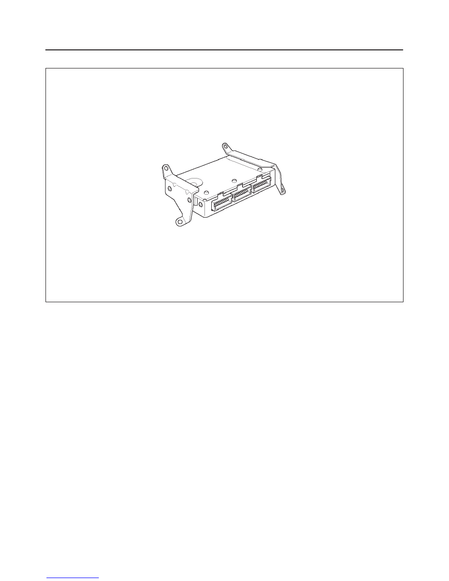
014RX002
Circuit Description
Output driver modules (ODMs) are used by the
powertrain control module(PCM) to turn ON many of the
current driven devices that are needed to control various
engine and transmission functions. Each ODM is capable
of controlling up to 11 separate outputs by applying
ground to the device which the PCM is commanding ON.
ODMs have the capability of diagnosing each output
circuit individually. DTC P1640 set indicates an improper
voltage level has been detected on an ODM output.
If the PCM detects an open circuit condition and a shorted
to voltage circuit condition on the same circuit at the same
time, then DTC P1640 will set. DTC P1640 is a type D
code.
Conditions for Setting the DTC
f
Ignition ON.
f
Above conditions occur for at least 2.5 seconds.
f
The PCM detects an open circuit condition and a
shorted to voltage circuit condition on the same circuit
at the same time.
Action Taken When the DTC Sets
f
The PCM will not illuminate the malfunction indicator
lamp (MIL).
f
The PCM will store conditions which were present
when the DTC was set as Failure Records only. This
information will not be stored as Freeze Frame data.
Conditions for Clearing the DTC
f
A history DTC P1640 will clear after 40 consecutive
warm up cycles occur without a fault.
f
DTC P1640 can be cleared by using the Scan Tool’s
”Clear Info” function.
Diagnostic Aids
Check for the following conditions:
f
Poor connection at PCM – Inspect harness connectors
for backed–out terminals, improper mating, broken
locks, improperly formed or damaged terminals, and
poor terminal to wire connection.
f
Damaged harness Inspect the wiring harness for
damage. If the harness appears to be OK, disconnect
the PCM, turn the ignition ON and observe a voltmeter
connected to the MIL driver circuit at the PCM harness
connector while moving connectors and wiring
harnesses relates to the MIL. A change in voltage will
indicate the location of the fault.
f
Reviewing the Failure Records vehicle mileage since
the diagnostic test last failed may help determine how
often the condition that caused the DTC to be set
occurs. This may assist in diagnosing the condition.
The following PCM pins are controlled by
output driver modules (ODMs):
f
A13 MIL LAMP
f
A14 Rear Defogger
f
B15 Up Shift
f
B14 A/C Clutch

6E1–353
RODEO X22SE 2.2L ENGINE DRIVEABILITY AND EMISSION
f
A15 EVAP Canister Vent Solenoid
f
B16 EVAP Canister Parge Solenoid
f
A1 2 Low Fuel
f
C10 Tacho Meter
f
C11 Fuel Gauge
f
C13 Fan Low
f
C12 Fan High
Test Description
Number(s) below refer to the step number(s) on the
Diagnostic Chart.
2. The Tech 2 Driver Module Status indicates the PCM
pin that is affected.
9. The Tech 2 may indicate “short circuit” even when
the problem is an open circuit. The cause of an
open circuit may be in the component itself.
11. A short to ground on the ignition side of the
component will blow the fuse. Since the fuse was
checked in Step 2, a short to ground would be
between the affected component and the PCM.
DTC P1640 –Output Driver Module (ODM) “A” Fault
Step
Action
Value(s)
Yes
No
1
Was the “On-Board Diagnostic (OBD) System Check”
performed?
—
Go to
Step 2
Go to
OBD
System
Check
2
Check the fuse for the driver circuit that was shown as
faulty.
Was the fuse blown?
—
Go to
Step 3
Go to
Step 4
3
1. Check for a short to ground between the fuse and
the affected component.
2. Replace the fuse after making any necessary
repairs.
Is the action complete?
—
Verify repair
—
4
1. Disconnect the PCM connector for the affected
driver circuit.
Is there any damage to the PCM pin or connector?
—
Go to
Step 5
Go to
Step 6
5
Repair the damaged pin or terminal.
Is the action complete?
—
Verify repair
—
6
Was the Lamp of circuit for “Check Engine”?
—
Go to
Step 7
Go to
Step 13
7
1. Leave the PCM connector for the lamp driver circuit
disconnected.
2. Ignition “ON.”
3. Using a DVM, check the voltage at the PCM
connector for the affected lamp driver circuit.
Was the voltage equal to the specified value?
B+
Go to
Step 15
Go to
Step 8
8
1. Ignition “ON.”
2. Check for battery voltage at the fuse for the affected
lamp circuit.
Was battery voltage available at the fuse?
—
Go to
Step 10
Go to
Step 9
9
Repair the open circuit between the ignition switch and
the fuse.
Is the action complete?
—
Verify repair
—
10
1. Ignition “OFF.”
2. Disconnect the PCM connector for the affected
driver terminal.
3. Connect an ohmmeter between a good ground and
the PCM connector for the affected driver.
Did the ohmmeter indicate continuity?
—
Go to
Step 11
Go to
Step 12

6E1–354
RODEO X22SE 2.2L ENGINE DRIVEABILITY AND EMISSION
DTC P1640 –Output Driver Module (ODM) “A” Fault
(Cont'd)
Step
No
Yes
Value(s)
Action
11
Repair the short to ground between the affected
component and its PCM driver terminal.
Is the action complete?
—
Verify repair
—
12
Repair the open circuit between the fuse and the PCM
driver terminal for the affected circuit.
Is the action complete?
—
Verify repair
—
13
1. Connect the PCM.
2. Start the engine and let it idle.
3. Backprobe the affected terminal at the PCM with a
DVM.
Was the voltage equal to the specified value?
B+
Go to
Step 15
Go to
Step 14
14
1. Run the engine at idle.
2. Check for battery voltage at the fuse for the affected
circuit.
Was battery voltage available at the fuse?
—
Go to
Step 10
Go to
Step 9
15
Replace the PCM.
IMPORTANT: The replacement PCM must be
programmed. Refer to
On-Vehicle Service in
Powertrain Control Module and Sensors for
procedures.
And also refer to latest Service Bulletin.
Check to see if the Latest software is released or not.
And then Down Load the LATEST PROGRAMMED
SOFTWARE to the replacement PCM.
Is the action complete?
—
Verify repair
—
Нет комментариевНе стесняйтесь поделиться с нами вашим ценным мнением.
Текст