Isuzu Rodeo UE. Manual — part 87
TRANSFER CASE
4D–11
Transfer Rear Case Assembly (A/T)
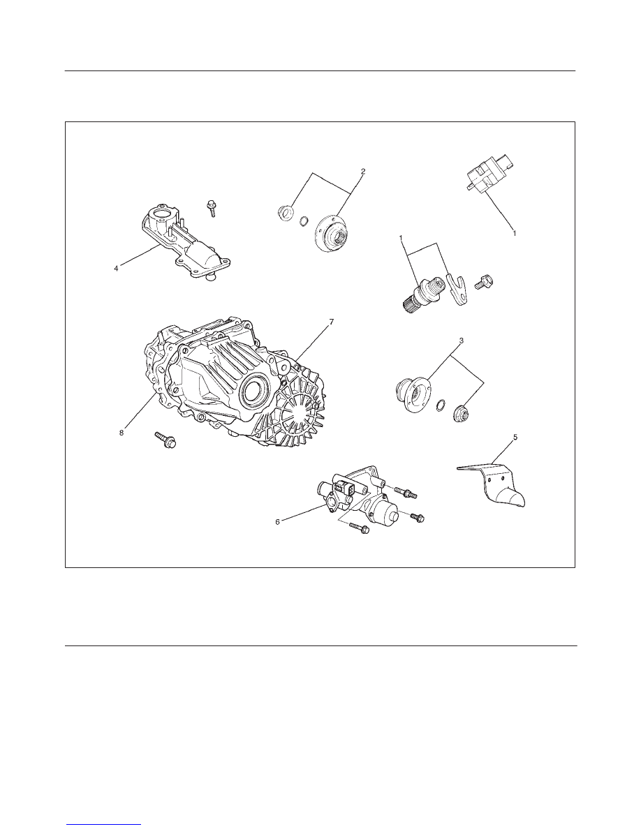
Transfer Rear Case Assembly (A/T) and Associated Parts
220RW133
Legend
(1) Speedometer Sensor, Speedometer Driven
Gear and Plate
(2) Front Companion Flange
(3) Rear Companion Flange
(4) Control Box Assembly
(5) 2WD–4WD Actuator Heat Protector
(6) 2WD–4WD Actuator Assembly
(7) Transfer Rear Cover Assembly
(8) Transfer Case Assembly
Removal
1. Remove the speedometer sensor (1).
2. Remove the plate (1).
3. Remove the speedometer driven gear bushing and
driven gear (1).
NOTE: Apply a reference mark to the driven gear bushing
before removal.
4D–12
TRANSFER CASE
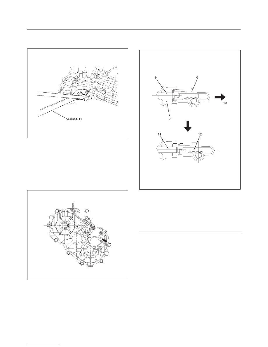
4. Remove front companion flange (2) and rear
companion flange (3), using the flange companion
holder J–8614–11 to remove the end nut..
262RW009
5. Remove the front and rear companion flange.
NOTE: Use the universal puller to remove the rear
companion flange.
6. Disconnect the actuator breather hose and transfer
breather hose from control box (4).
7. Remove control box assembly (4).
8. Disconnect the actuator breather hose and
2WD–4WD actuator heat protector (5) from the
2WD–4WD actuator assembly (6).
220RW002
9. Remove the 2WD–4WD actuator assembly bolts.
10. Pull the 2WD–4WD actuator assembly (6) with
2WD–4WD shift rod.
220RW065
Legend
(6) 2WD–4WD Actuator Assembly
(7) Rear Cover Assembly
(9) Shift Rod: 2WD–4WD (Position: 2WD)
(10) Pull
(11) Position: 4WD
(12) Mode: 2WD
TRANSFER CASE
4D–13
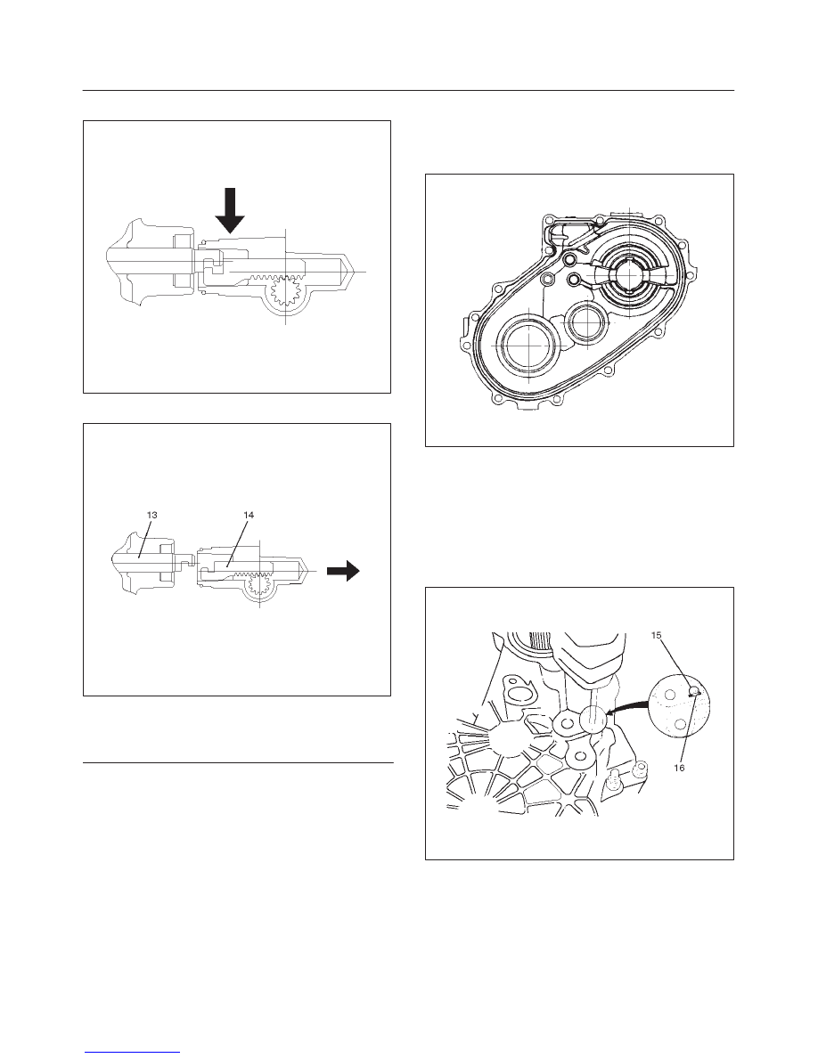
11. Off set the actuator assembly.
220RW028
12. Remove the actuator assembly (6).
220RW066
Legend
(13) Position: 4WD
(14) Mode: 2WD
13. Remove transfer rear cover assembly (7) from
transfer case assembly.
Installation
1. Apply the recommended liquid gasket (LOCTITE
17430) or its equivalent to the transfer rear cover
fitting faces.
220RS017
2. Install transfer rear cover assembly (7) to transfer
case assembly (8).
3. Perform the following steps before fitting the transfer
rear case.
1. Shift the high–low shift rod to the 4H side.
2. The cut–away portion of the select rod head (15)
should align with that of the rear case hole’s
stopper (16).
230RW009
4D–14
TRANSFER CASE
4. Tighten the transfer rear case bolts to the specified
torque.
Torque: 37 N·m (27 lb ft)
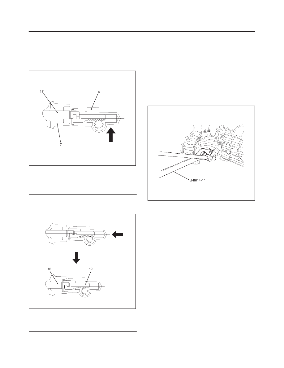
5. Shift the 2WD–4WD shift rod (17) to the 4WD side.
6. Join the rod grooves of 2WD–4WD actuator
assembly (6) and shift rod (17).
220RW067
Legend
(6) 2WD–4WD Actuator Assembly (Mode: 2WD)
(7) Rear Cover Assembly
(17) Shift Rod: 2WD–4WD (Position: 4WD)
7. Push the 2WD–4WD actuator assembly (6) with
2WD–4WD shift rod (17) till the shift rod (17) reaches
the 2WD position.
220RW068
Legend
(18) Position: 2WD
(19) Mode: 2WD
8. Tighten the 2WD–4WD actuator bolts to the specified
torque.
Torque: 19 N·m (14 lb ft)
9. Connect the actuator breather hose to actuator.
10. Install actuator heat protector (5).
11. Install control box assembly (4).
Torque: 19 N·m (14 lb ft)
12. Connect breather hoses to control box (4).
13. Install rear companion flange (3) and front companion
flange (2), using the companion flange holder
J–8614–11 to tighten the flange nuts to the transfer
case.
262RW009
14. Tighten the new transfer flange nuts to the specified
torque.
Torque
Rear companion flange: 167 N·m (123 lb ft)
Front companion flange: 137 N·m (101 lb ft)
Нет комментариевНе стесняйтесь поделиться с нами вашим ценным мнением.
Текст