Isuzu Rodeo UE. Manual — part 593
8D–220
WIRING SYSTEM
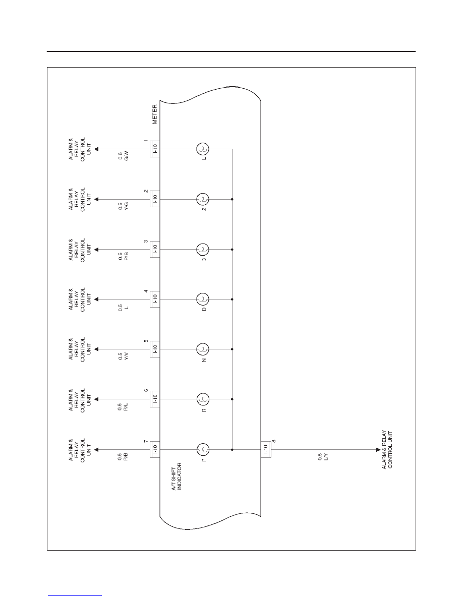
Circuit Diagram – 6
D08RX127
8D–221
WIRING SYSTEM
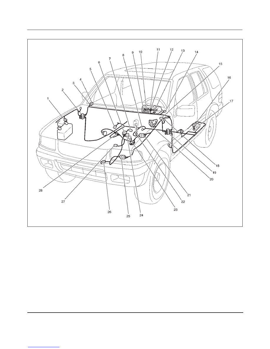
Parts Location
D08RX133
Legend
(1) H–2
(2) H–12, H–13, H–14, H–19
(3) I–41, I–42
(4) Alarm & Relay Control Unit
(5) E–6
(6) M–11
(7) M–10
(8) B–8
(9) I–1
(10) I–10
(11) Combination Meter
(12) I–2
(13) I–9
(14) I–7
(15) I–14
(16) Fuel Tank Unit
(17) Fuel Tank
(18) C–16
(19) H–15, H–16, H–17, H–31, H–32
(20) C–6
(21) H–5, H–6
(22) B–23
(23) M–3, M–4
(24) M–12
(25) H–10
(26) C–15
(27) E–1
(28) M–1, M–2

8D–222
WIRING SYSTEM
Diagnosis
Speedometer
Speedometer and Odometer Do Not Function
Step
Action
Value(s)
Yes
No
1
Does the vehicle speed sensor output in 4 pulses/1
rotation?
—
Go to Step 2
Replace the
vehicle speed
sensor
2
Are the circuits between the vehicle speed sensor and
the meter, and the fuse (11) and the ground normal?
—
Replace the
speedometer
Repair a poor
connection at
the
connectors or
an open
circuit in the
circuit
Speedometer Does Not Function (Odometer Is Normal)
Step
Action
Value(s)
Yes
No
1
Replace the speedometer assembly
Is the action complete?
—
Verify repair
—
Odometer Does Not Function (Speedometer Is Normal)
Step
Action
Value(s)
Yes
No
1
Replace the speedometer assembly
Is the action complete?
—
Verify repair
—
Speedometer Needle Fluctuates (May Be Wide Fluctuation)
Step
Action
Value(s)
Yes
No
1
Does the vehicle speed sensor normally?
—
Go to Step 2
Replace the
speedometer
2
1. The oscilloscope waveform is deformed.
2. Replace the vehicle speed sensor, or repair a poor
connection at the connectors in the circuit or a
failure in the cable harness.
Is the action complete?
—
Verify repair
—
Speedometer Needle Jumps Erratically
Step
Action
Value(s)
Yes
No
1
Does the vehicle speed sensor output normally?
—
Go to Step 2
Replace the
speedometer
2
An abnormal perodic waveform is output by
oscilloscope.
Replace the vehicle speed sensor, or repair a poor
connection at the connectors in the circuit or a failure in
the cable harness.
Is the action complete?
—
Verify repair
—

8D–223
WIRING SYSTEM
Inspection Of Waveform By Oscilloscope
Step
Action
Value(s)
Yes
No
1
1. Disconnect the battery ground cable.
2. Remove four screws of the meter assembly.
3. Connect a resistance of 1.3 to 5k ohm (1.4W or
more) between the harness side connector I–1
terminal 12 and I–2 terminal 12 of the meter.
4. Install a speedometer tester.
5. Turn on the starter SW.
6. Check the waveform at the time when the vehicle
speed is at 37 mph.
Is the pulse input normal?
—
Replace the
speedometer
Replace the
vehicle speed
sensor, or
repair a poor
connection of
the
connectors in
the circuit or
a failure in
the cable
harness.
Tachometer
Tachometer Needle Fluctuates (May Be Wide Fluctuation)
Step
Action
Value(s)
Yes
No
1
Is the pulse input normal?
—
Replace the
tachometer
Go to Step 2
2
Replace the PCM, repair a poor connection of the
connector in the circuit or a failure in the cable harness.
Is the action complete?
—
Verify repair
—
Tachometer Needle Jumps Erratically
Step
Action
Value(s)
Yes
No
1
Is the pulse input normal?
—
Replace the
tachometer
Go to Step 2
2
Replace the ignition control module, or repair a poor
connection of the connector in the circuit or a failure in
the cable harness.
Is the action complete?
—
Verify repair
—
Engine Coolant Temperature Gauge
Needle Does Not Move
Step
Action
Value(s)
Yes
No
1
Is the connector of the engine coolant temperature unit
connected securely?
—
Go to Step 2
Connect the
connector
securely
2
Disconnect the connector of the engine coolant
temperature unit.
Connect a 3.4 W bulb between the harness side
connector E–19 terminal 1 and the ground of the
thermo unit.
When the starter SW is turned ON, does the gauge
pointer move about 10 seconds after that?
—
Go to Step 3
Go to Step 4
Нет комментариевНе стесняйтесь поделиться с нами вашим ценным мнением.
Текст