Isuzu KB P190. Manual — part 785
Engine Cooling – V6 Engine
Page 6B1–5
2 General
Description
2.1 Radiator
Assembly
The radiator has an aluminium core and is of the cross-flow design. Plastic side tanks are attached to the core by clinch
tabs. The clinch tabs are formed as part of the core assembly.
The lower frame of the radiator assembly is attached to the vehicle frame by two bolts supported in rubber mounts, pegs
are attached to the upper area of each side tank. These pegs are used to support the radiator with two rubber insert
mounting brackets.
A high temperature rubber seal is used to seal the mating surface between the core and each side tank. The seal(s)
must be replaced any time the side tank is removed from the core.
N O T E
The radiator core side tanks or transmission oil
cooler cannot be replaced separately. If there is a
fault with any of these components, the radiator
assembly must be replaced. Small core repairs
may be made using an aluminised silicon based
liquid repair agent. Refer to 3.15
Radiator
in
this Section.
For vehicles with automatic transmission, a transmission oil cooler is located in the right-hand side radiator tank. The
cooler pipes from and to the transmission are connected to the oil cooler flexible hoses by means of quick connect
fittings.
The cooling fan motor is attached by three screws to the one-piece plastic fan shroud. In turn, the fan shroud is mounted
to the rear of the radiator and is located and supported by two bolts and two locating tabs. The upper clips lock the fan
shroud in place and can be released by hand to facilitate fan shroud removal. The shroud must be removed to allow fan
motor and blade assembly removal.
One harness connector is mounted to the upper section of the fan shroud allowing the fan motor and blade assemblies
to be removed individually from the shroud. The fan motor and blade is balanced as an assembly. These two
components are serviced only as a unit and are not to be separated.
The shroud, fan assembly and transmission cooler hoses can be removed and installed individually from the vehicle. For
removal and installation procedures, refer to 3.13Cooling Fan and Shroud Assembly, 3.14
Flexible Transmission
Cooler Hose and 3.15 Radiator in this Section.
Engine Cooling – V6 Engine
Page 6B1–6
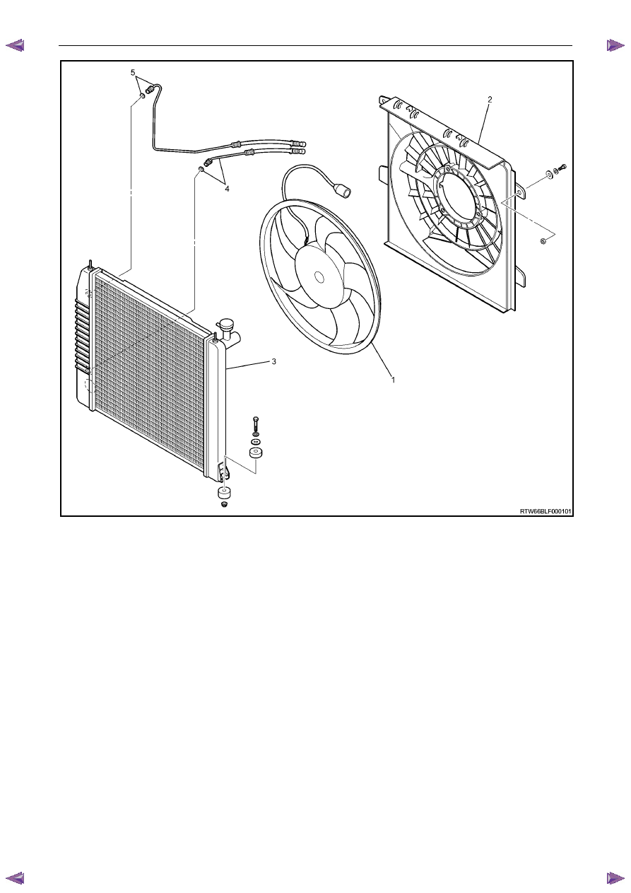
Figure 6B1 – 1
Legend
1
Fan and Motor Assembly
2 Fan
Shroud
3 Radiator
4
Lower Transmission Cooling Line and Seal
5
Upper Transmission Cooling Line and Seal
Engine Cooling – V6 Engine
Page 6B1–7
2.2
Cooling Fan – Standard Specification
Overview
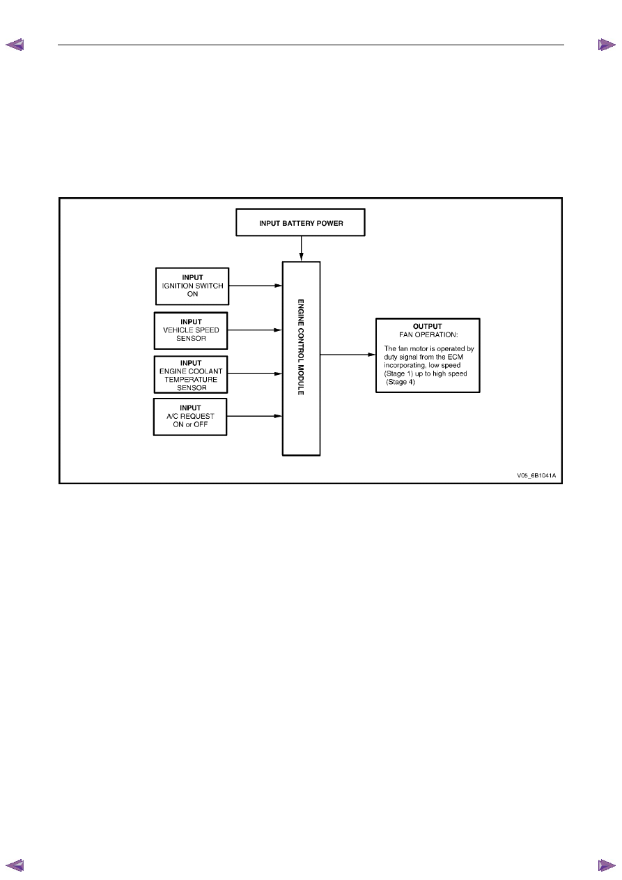
The fan is a standard cooling system rated at 400 Watts with a blade diameter of 500 mm, which consists of a single
four speed fan. The fan motor is operated by duty signal from the ECM incorporating, low speed (Stage 1) up to high
speed (Stage 4).
The following outlines the operation of the cooling system, at block level, also showing what inputs the Engine Control
Module (ECM) requires.
Figure 6B1 – 2
Engine Cooling – V6 Engine
Page 6B1–8
Cooling Fan and Shroud Assembly
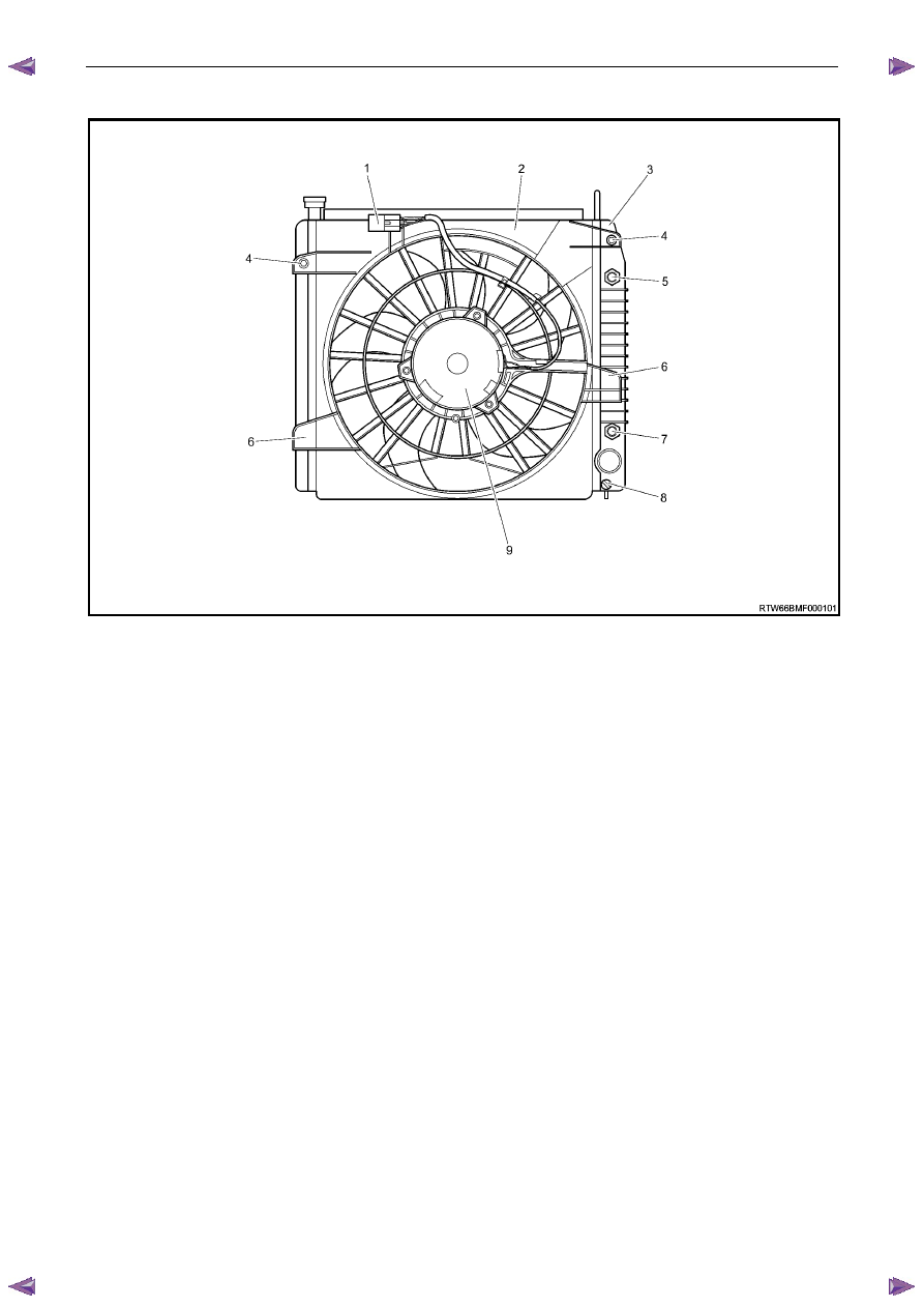
Figure 6B1 – 3
Legend
1
Fan Harness Connector
2 Fan
Shroud
3 Radiator
4
Fan Shroud Upper Support
5
Oil Cooler, Upper Line Connection (Auto Trans Only)
6
Fan Shroud Lower Support
7
Oil Cooler, Lower Line Connection (Auto Trans Only)
8
Radiator Drain Tap
9 Fan
Motor
Fan Motor
When the Standard Cooling Fan System is fitted to the HFV6 engine, the fan motor is 12 Volt and variable-speed. The
internal construction of the fan motor consists of two brushes and two permanent magnets. A three-wire pigtail harness is
permanently connected to the motor and is attached to the polypropylene fan shroud by integral clips moulded as part of
the fan shroud.
The enclosed fan motor housing is constructed of yellow zinc coated steel. A drain hole is located in the bottom of the
housing to allow for breathing and draining of any moisture ingress.
The fan motor rotates in an anticlockwise direction when viewed from the fan motor side.
The motor is rated at 400 Watts and drives a (500 mm) diameter fan blade at approximately 2,400 ± 240 rpm at high
speed (stage 4).
The fan and motor is balanced as a unit and the fan blade must not be separated from the motor. The fan motor and
blade are serviced only as an assembled unit. However, it should be noted that the central nut attaching the fan blade to
the motor shaft has a left-hand thread.
Fan Operation
On vehicles with HFV6 engines, the engine cooling fan motor has three terminals; one positive and one negative and
one the drive signal from the ECM. The positive terminal is permanently connected to battery voltage, via fuse SBF –3.
The cooling fan operation is enabled when the ECM via connector C – 56, pin 20 supplies a duty signal which varies
dependant on the engine temperature, vehicle speed, A/C request (where fitted) and A/C system pressure, the speed
varies from low speed (Stage 1) up to high speed (Stage 4). Refer to 6C1 – 1 Engine management general information.
Нет комментариевНе стесняйтесь поделиться с нами вашим ценным мнением.
Текст