Isuzu KB P190. Manual — part 786
Engine Cooling – V6 Engine
Page 6B1–9
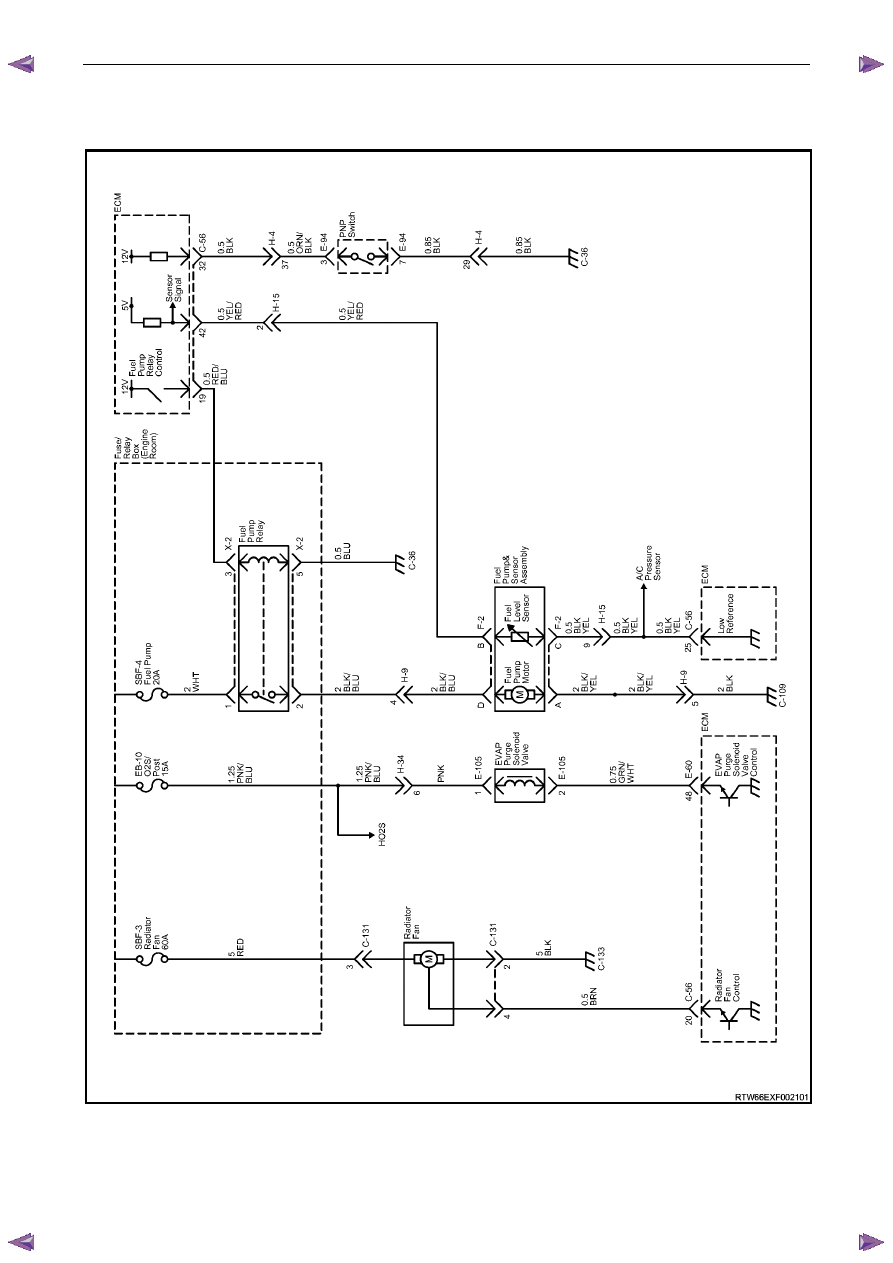
V6 Cooling Fan Wiring Diagram
Figure 6B1 – 4
Engine Cooling – V6 Engine
Page 6B1–10
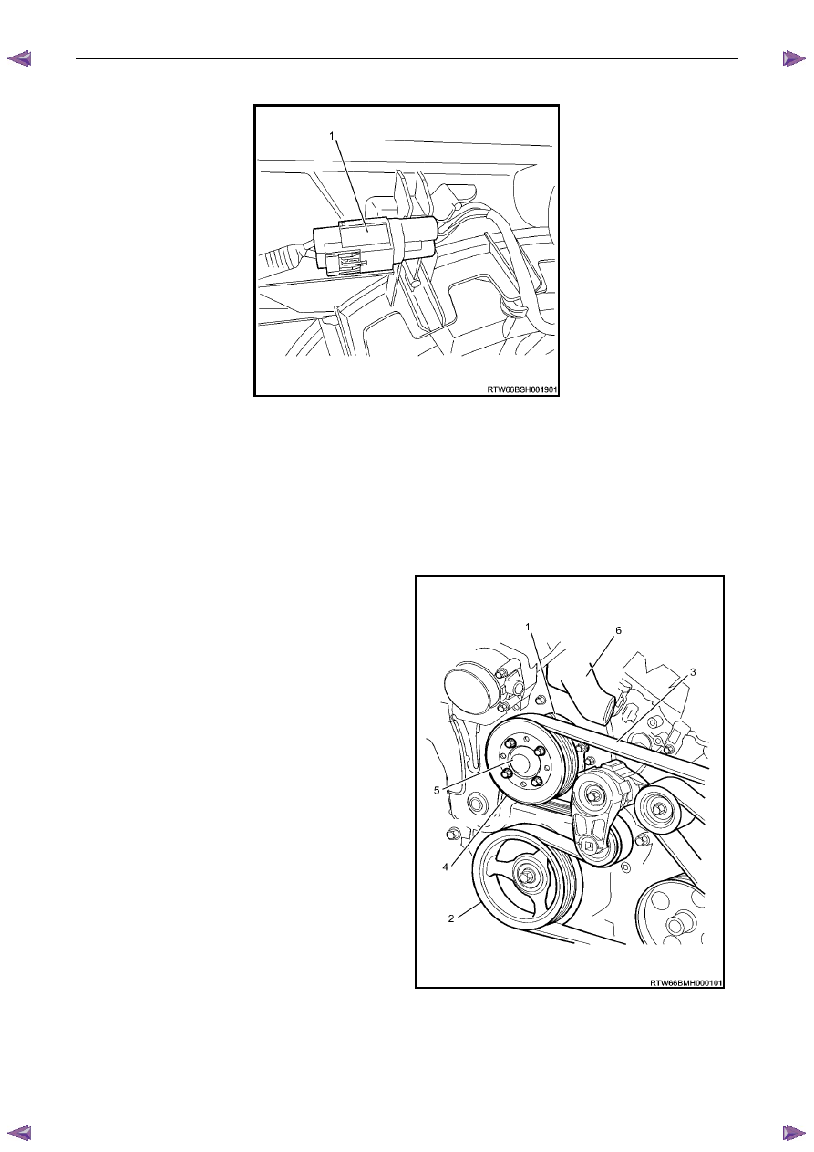
Fan Assembly connector
Figure 6B1 – 5
2.3 Coolant
Pump
The coolant pump is a centrifugal vane impeller type pump. The pump consists of a housing and an impeller. The
impeller is a flat plate mounted on the pump shaft with a series of flat or curved blades (vanes). When the impeller
rotates, the coolant between the vanes is thrown outward by centrifugal force. The impeller shaft is supported by sealed
bearings. The sealed bearings do not need to be lubricated. Grease cannot leak out, dirt and water cannot get in as long
as the seal is not damaged or worn.
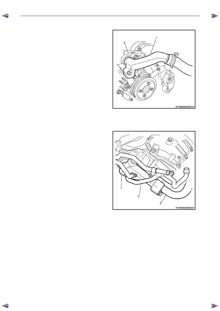
The coolant pump (1) is mounted to the engine front cover
and is driven by the crankshaft pulley (2) via a multi-ribbed
drive belt (3), turning the pump pulley (4), bolted to the
coolant pump flange (5). Coolant enters the engine
through the coolant inlet pipe and thermostat at the rear of
engine and passes through the engine to the coolant
pump on the front engine cover and exits via the coolant
outlet housing (6) located at the front of the intake
manifold.
Figure 6B1 – 6
Engine Cooling – V6 Engine
Page 6B1–11
2.4
Coolant Outlet Housing
The coolant outlet housing (1) is located at the front of the
intake manifold (2).
Figure 6B1 – 7
2.5 Thermostat
The thermostat housing (1) is located at the rear of the
engine between the coolant inlet pipe (2) and the rear of
the intake manifold, underneath the heater pipe assembly
(3).
Figure 6B1 – 8
Engine Cooling – V6 Engine
Page 6B1–12
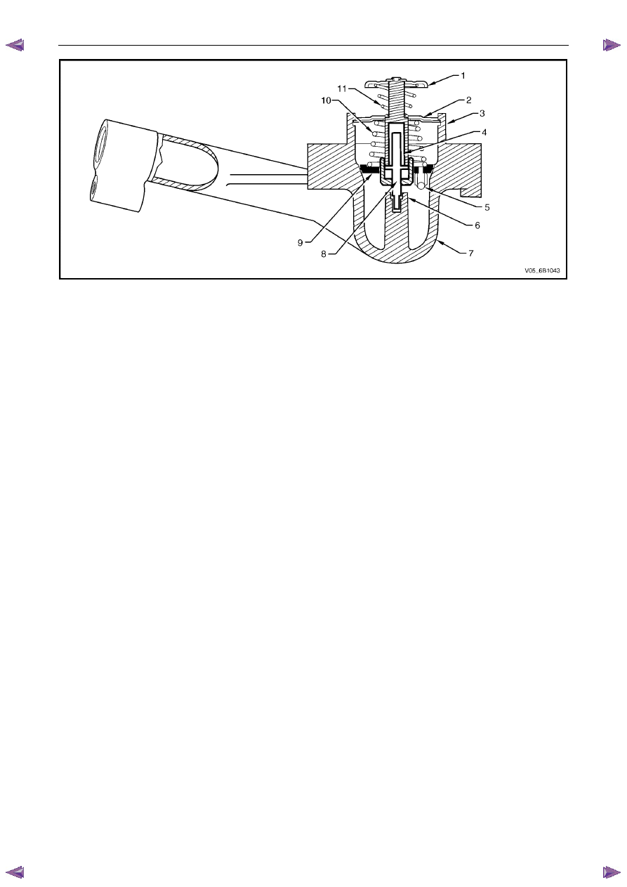
Figure 6B1 – 9
Legend
1 Bypass
Valve
2
Thermostat Retaining Bar
3
Thermostat Assembly Retaining Lugs
4 Wax
Pellet
5
Air Bleed Valve
6
Piston Centre Support
7 Thermostat
Housing
8 Piston
9 Rubber
Diaphragm
10 Thermostat
Spring
11 Bypass
Spring
A wax pellet type thermostat is used in the coolant inlet passage to control the flow of coolant, providing fast engine
warm up and regulating coolant temperature. The wax pellet or power element in the thermostat expands when heated
and contracts when cooled. The wax pellet is connected through a piston to a valve and when the pellet is heated,
pressure is exerted against a metal valve, which is forced to open.
As the pellet is cooled, the contraction allows a spring to close the valve. Thus, the valve remains closed while the
coolant is cold, preventing circulation of coolant through the radiator, but allowing the coolant to circulate throughout the
engine to warm it quickly and evenly. As the engine becomes warm, the pellet expands and the thermostat opens,
permitting the coolant to flow through to the radiator where heat is transferred to the surrounding air, through the radiator
walls.
This opening and closing of the thermostat valve permits enough coolant to enter the radiator to keep the engine within
specified temperature limits.
The thermostat also provides a restriction in the cooling system, even after it has opened. This restriction creates a
pressure difference, which prevents cavitation at the coolant pump and forces coolant to circulate through the engine
block.
Нет комментариевНе стесняйтесь поделиться с нами вашим ценным мнением.
Текст