Isuzu KB P190. Manual — part 901
Charging System – V6
Page 6D1-1-17
4.2
Generator Mounting Bracket
Remove
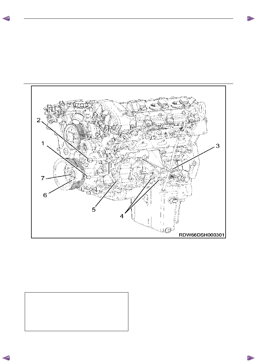
1
Remove the idler pulley bolt (7) then the idler pulley (6), Refer to 4.1 Generator.
2
Remove the bolts (1, 2, 3 ,4); five places attaching the generator mounting bracket (5) to the engine block.
3
Remove the generator mounting bracket from the vehicle.
Figure 6D1-1 6
Reinstall
Reinstallation of the generator mounting bracket and generator is the reverse of the removal procedure, noting the
following:
1
Tighten all fasteners to the correct torque specification.
2
Reinstall the generator, refer to 4.1
Generator.
Generator mounting bracket bolts ... (1) 40.0 – 60.0 Nm
Generator mounting bracket bolts ... (2) 100.0 Nm
Generator mounting bracket bolts ... (3) 40.0 – 60.0 Nm
Generator mounting bracket bolts ... (4) 40.0 – 60.0 Nm
Idler pulley bolt. . . . . . . . . (7) 58.0 Nm
Charging System – V6
Page 6D1-1-18
4.3
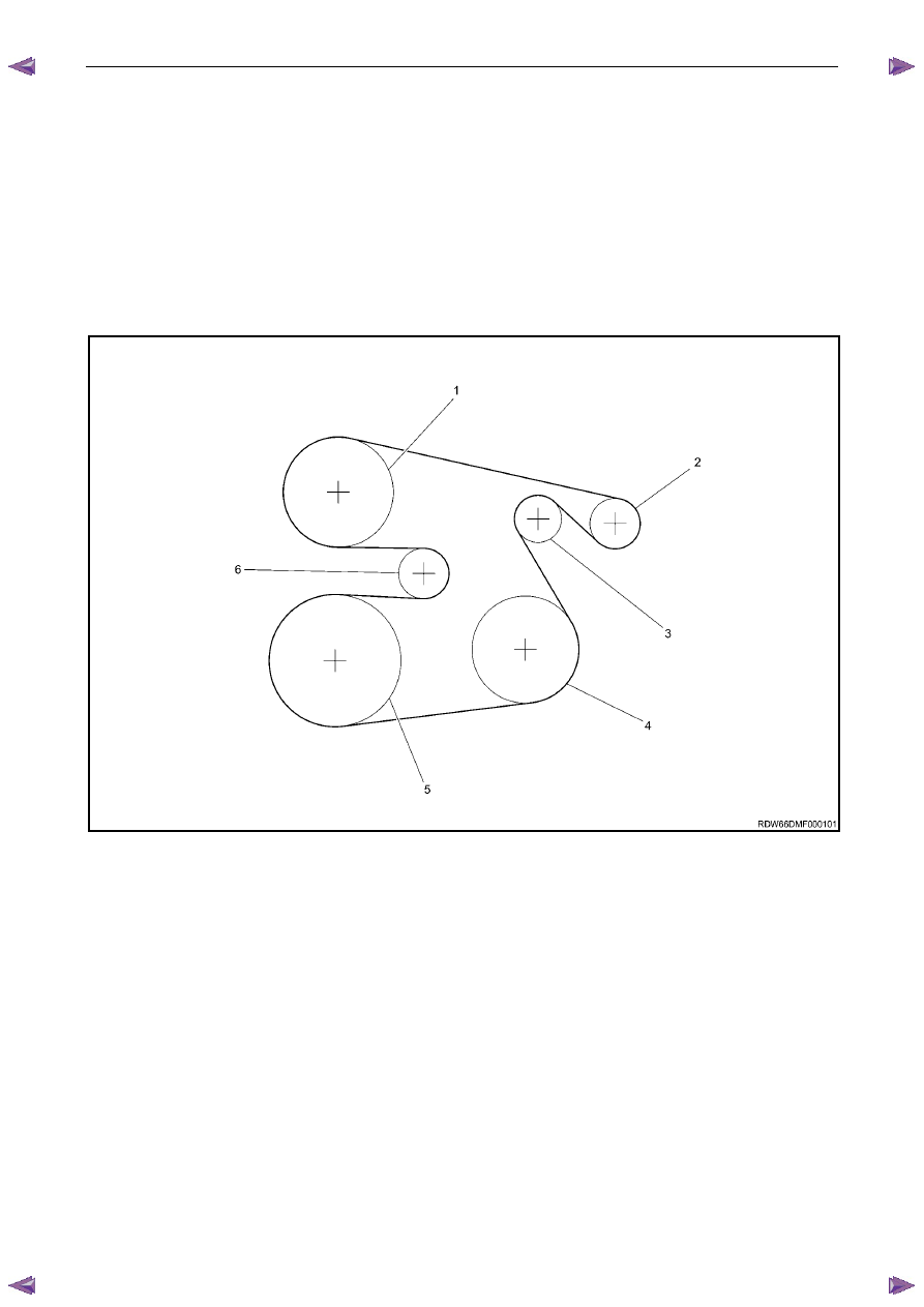
Drive Belt Routing
Without Air Conditioning
Ensure the drive belt ribs are correctly positioned in all pulleys and the crankshaft balancer.
N O T E
For detailed information relating to drive belt
service procedure, refer to 6A1 Engine
Mechanical.
Figure 6D1-1 7 shows the drive belt routing for the HFV6 engine without air-conditioning.
Figure 6D1-1 7
Legend
1 Water
Pump
2 Generator
3 Idler
4 Power
Steering
5 Crankshaft
6 Tensioner
Charging System – V6
Page 6D1-1-19
6 Specifications
Ground Polarity. . . . . . . . . . . . . . . . . . . . . . . . . . ...Negative
Nominal Voltage . . . . . . . . . . . . . . . . . . . . . . . . . . . ... 12 V
Nominal Output. . . . . . . . . . . . . . . . . . . . . . . . . . . ... 120 A
Stator Phases . . . . . . . . . . . . . . . . . . . . . . . . . . . . . . .3
Stator Winding Connections. . . . . . . . . . . . . . . . . . . . . . . Delta
Voltage Regulator Setting. . . . . . . . . . . . . . . . . . . . ... 14.2 – 14.8 V
Rotor Winding Resistance @ 20
°C . . . . . . . . . . . . . . . . . . . . . 2.1 V
Slip-ring Outer Diameter. . . . . . . . . . . . . . . . . . . . . . . .22.7 mm
Slip-ring Service Limit. . . . . . . . . . . . . . . . . . . . . . . . .22.1 mm
Stator Winding Resistance @ 20
°C . . . . . . . . . . . . . . . . . . . 0.098 Ω
Brush Length New . . . . . . . . . . . . . . . . . . . . . . . . . ..18.5 mm
Minimum Brush Length. . . . . . . . . . . . . . . . . . . . . . . . .5.0 mm
Direction of Rotation (viewed from pulley) . . . . . . . . . . . . . . . . Clockwise
Charging System – V6
Page 6D1-1-20
7
Torque Wrench Specifications
. . . . . . . . . . . . . . . . . . . . . . . . . . . . . . Nm
Generator Mounting Bolts (1, 2, 4) . . . . . . . . . . . . . . . ..58.0
Generator Mounting Bracket Bolts (1, 3, 4). . . . . . . . . ..40.0 – 60.0
Generator Mounting Bracket Bolts (2). . . . . . . . . . . . . . ...0.0
Battery Harness to G8 – X1 pin A Nut. . . . . . . . . . . . 5.0 – 12.0
Нет комментариевНе стесняйтесь поделиться с нами вашим ценным мнением.
Текст