Isuzu KB P190. Manual — part 900
Charging System – V6
Page 6D1-1-13
20
Reduce the engine speed to idle.
On completion of the generator output test,
return the engine to idle and disconnect the
loading device from the battery terminals.
This prevents excessive battery discharge.
21
Stop the engine.
22
Disconnect the battery ground cable P-5 at the battery.
23
Remove the multimeters.
24
Reconnect the generator positive lead P-9.
25
Reconnect the battery ground cable P-5 to the battery.
Engine RPM. . . . . . . . . . . . . . . 1900
Load. . . . . . . . . . . . . . . . 5.0 – 10 A
Output Voltage. . . . . . . . . . ...13.8 – 15.4 V
Charging Circuit Voltage Drop Test
Prerequisites
Before testing the generator output, ensure that:
•
all generator circuit connections are clean and tight,
•
the generator is always connected to the battery during testing (to prevent damage to the diodes),
•
the battery is fully charged, and
•
the specific gravity does not vary more than 0.025 between cells. (It is recommended the average specific gravity
is 1.260 or higher). Refer to 6D1-3 Battery – V6.
Carry out a load test on the battery to determine its ability to supply and accept current. This is a good indicator of the
general condition of the battery. For details of battery testing, refer to 6D1-3 Battery – V6.
Inspect the drive belt and tensioner markings to determine if the drive belt is within operating limits. Replace the belt if it
is excessively worn or outside the operating range of the tensioner.
For further details, refer to 6A1 Engine Mechanical – V6.
Voltage Drop Test
Ensure the generator connections are clean
and tight.
1
Connect the positive lead of a multimeter set to measure voltage to the generator terminal P-9.
2
Connect the negative lead of the multimeter to the battery positive post.
3
Switch the headlamps on.
4
Start the engine.
5
Increase the engine speed to approximately 2500 r.p.m.
6
Record the voltage reading.
7
Reduce the engine speed to idle.
Charging System – V6
Page 6D1-1-14
8
Connect the positive lead of a multimeter set to measure voltage to the battery negative post.
9
Connect the negative lead of the multimeter to the generator housing.
9
Increase the engine speed to approximately 2500 r.p.m.
10
Record the voltage reading.
11
Reduce the engine speed to idle.
12
Check the two readings. If the readings exceed 0.3 V, there is a high resistance in the charging circuit.
13
Trace the cause and correct the problem, refer to 8A Electrical Body and Chassis.
Charging System – V6
Page 6D1-1-15
4
Major Service Operations
4.1 Generator
Remove
Refer to 1.2 WARNING, CAUTION and NOTES
before disconnecting the battery.
1
Disconnect the battery ground lead P-5. Refer to 8A Electrical Body and Chassis.
2
Insert a ½ inch drive socket bar into the tensioner arm and rotate the tensioner arm clockwise.
3
Remove the drive belt from the generator pulley and release the tensioner. Refer to 6A1 Engine Mechanical – V6
for further details as required.
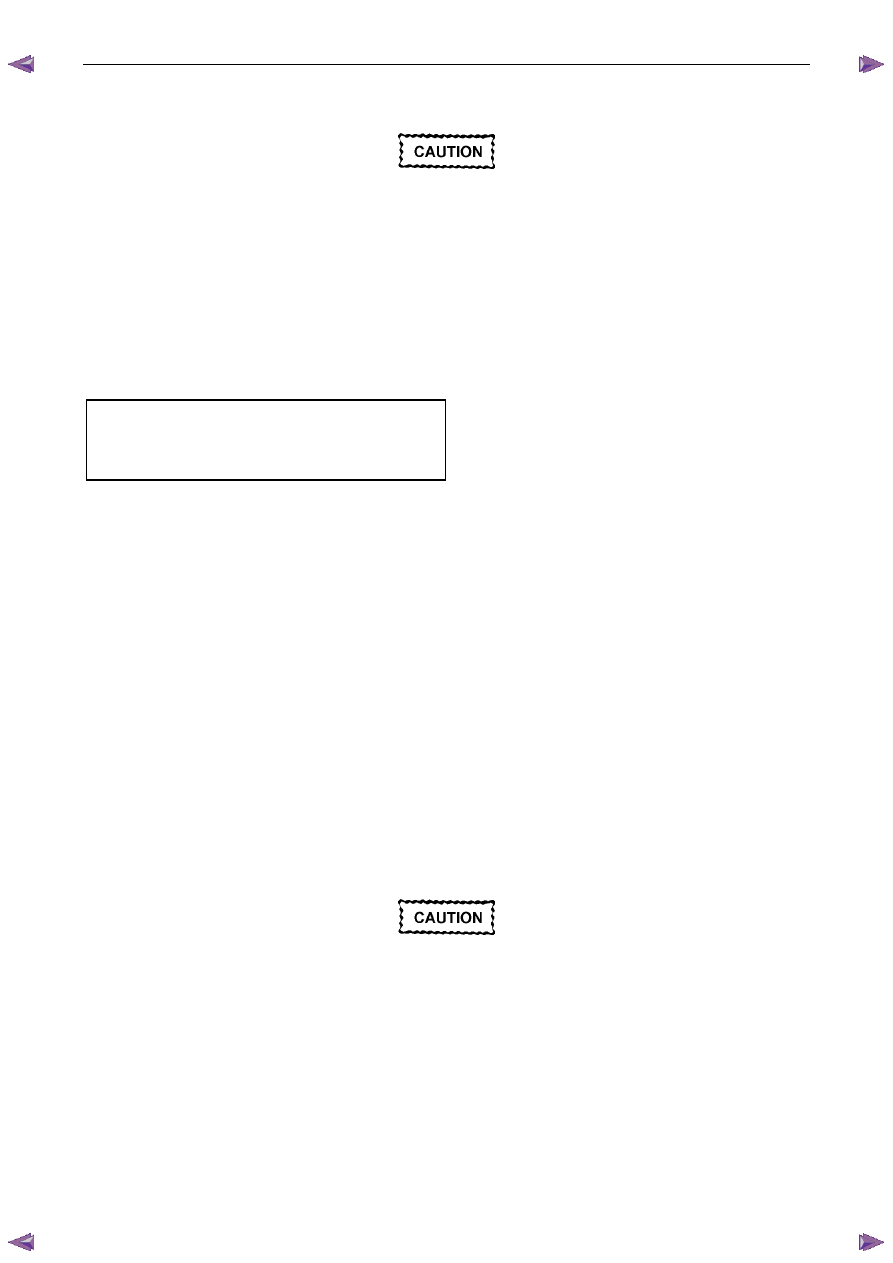
4
Pull the battery harness cap back from generator
terminal P-9 (3), remove the nut (4) and remove the
positive lead (2) from the generator (5).
5
Disengage the connector retaining clip and remove
the connector E-4, (1) from the generator.
Figure 6D1-1 4
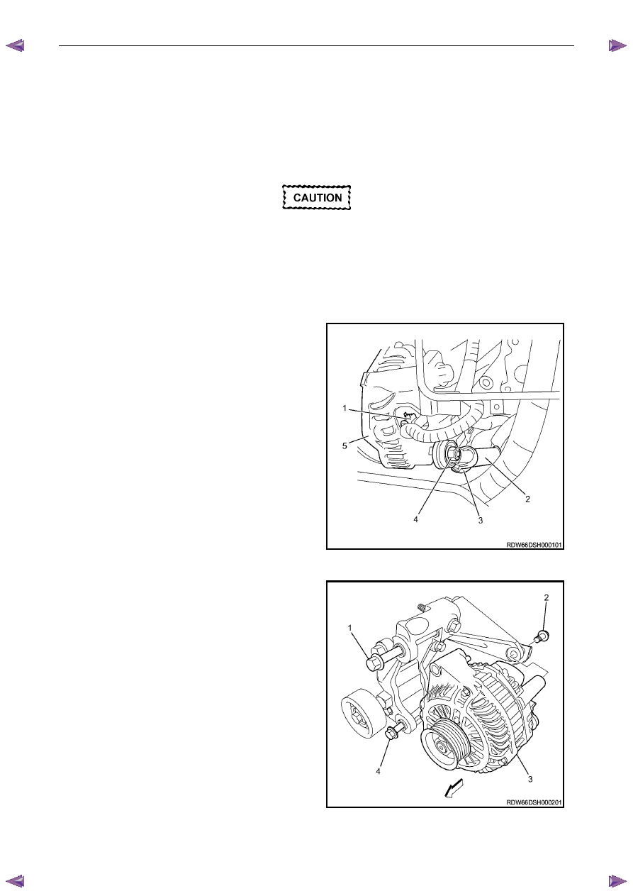
6
Remove the three bolts (1, 2, 4) retaining the
generator (3) to the generator bracket.
7
Remove the generator assembly from the vehicle.
Figure 6D1-1 5

Charging System – V6
Page 6D1-1-16
Reinstall
Reinstallation of the generator is the reverse of the removal procedure, noting the following:
1
Tighten all fasteners to the correct torque specification.
2
Reconnect the battery ground lead.
3
Start the engine.
4
Check the generator warning indicator operation.
5
Check the drive belt is correctly routed and aligned.
6
Check the generator output. Refer to 3.3
On-vehicle Testing.
7
Check the voltage regulator operation. Refer to 3.3 On-vehicle Testing.
8
Turn the ignition switch off.
Generator mounting bolts . . . . . . ... (1) 58.0 Nm
Generator mounting bolts . . . . . . ... (2) 58.0 Nm
Generator mounting bolts . . . . . . ... (4) 58.0 Nm
Battery harness to P-9 pin B nut
torque specification. . . . . . . . ...7.1 – 13.3 Nm
Нет комментариевНе стесняйтесь поделиться с нами вашим ценным мнением.
Текст