Isuzu KB P190. Manual — part 1151
7B-40 MSG MODEL
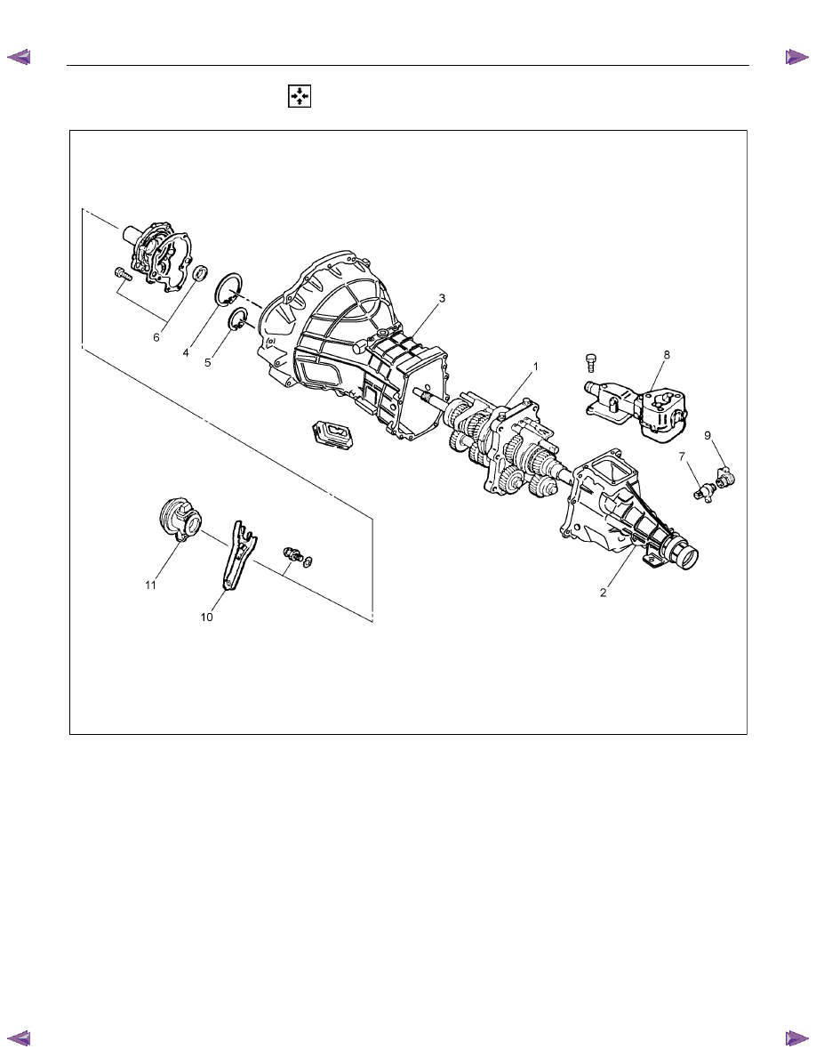
MAJOR COMPONENTS
RTW47BLF000401
Reassembly steps
1. Intermediate plate with gear assembly
▲ 2. Rear cover with oil seal
▲ 3. Transmission case
▲ 4. Bearing snap ring
5. Counter gear snap ring
▲ 6. Front cover with oil seal
7. Speedometer driven gear
8. Gear control box assembly
9. Speedometer sensor
10. Clutch shift fork
11. Clutch shift block and release bearing
MSG MODEL 7B-41
RTW47BSH000201
Important Operations
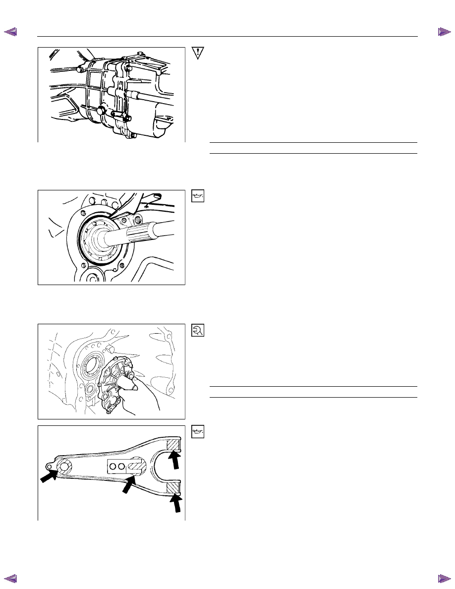
2. Rear Cover with Oil Seal
1) Align the pins at the lower side of the rear cover with the
holes in the lower side of the intermediate plate.
2) Apply recommended liquid gasket (Three Bond TB1215) or
its equivalent to the rear cover fitting surfaces.
3) Install the rear cover to the intermediate plate.
4) Tighten the rear cover bolts to the specified torque.
Rear Cover Bolt Torque
N
⋅m(kgf⋅m/lb⋅ft)
37 (3.8 / 27)
Note:
Take care not to twist or puncture the oil seal during the
installation procedure.
RTW47BSH000301
3. Transmission Case
4. Bearing Snap Ring
1) Apply the engine oil to the transmission case top gear shaft
ball bearing fitting faces.
2) Apply recommended liquid gasket or its equivalent to the
transmission case fitting surfaces.
3) Install the transmission case to the intermediate plate.
4) Pull the top gear shaft from the transmission case until the
ball bearing snap ring grove protrudes from the
transmission case front cover fitting faces.
5) Use a pair of snap ring pliers to install the snap ring to the
ball bearing.
6. Front Cover with Oil Seal
1) Clean and apply recommended liquid gasket or its
equivalent to the through bolt threads.
2) Install the new gasket and tighten the new cover bolt to the
specified torque.
Front Cover Bolt Torque
N
⋅m(kgf⋅m/lb⋅ft)
25 (2.5 / 18)
RTW47BSH000101
10. Shift Fork
Apply molybdenum disulfide type grease to the areas as
shown in the figure and install shift fork (Diesel engine).
7B-42 MSG MODEL
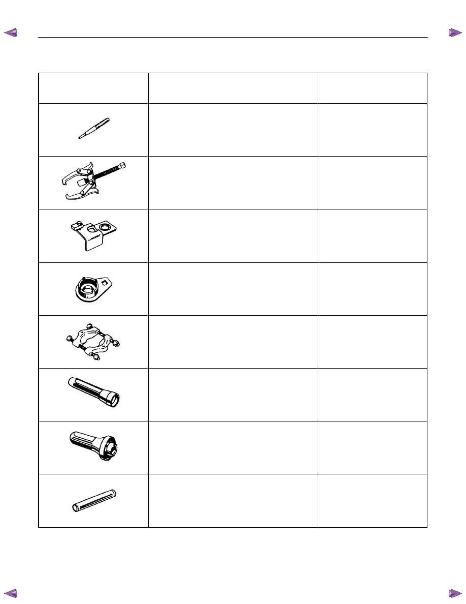
SPECIAL SERVICE TOOL
ILLUSTRATION
PART NO.
PART NAME
9-8529-2201-0
Spring pin remover
5-8840-0013-0
(J-22888)
Gear remover
5-8840-2001-0
(J-29768)
Holding fixture
5-8840-0353-0
(J-36629)
Lock nut wrench
5-8840-0015-0
(J-22912-01)
Bearing remover/installer
5-8840-0026-0
(J-26540)
Oil seal installer
5-8522-0050-0
(J-29769)
Oil seal installer
5-8840-0178-0
(J-33851)
Collar installer
MANUAL TRANSMISSION 7B1-1
SECTION 7B1
MANUAL TRANSMISSION
(MUA)
TABLE OF CONTENTS
PAGE
MUA5G/5H/5S (4
××××2)
Service Precaution . . . . . . . . . . . . . . . . . . . . . . . . . . . 7B1 – 3
General Description . . . . . . . . . . . . . . . . . . . . . . . . . . 7B1 – 4
Rear Oil Seal . . . . . . . . . . . . . . . . . . . . . . . . . . . . ... 7B1 – 5
××××2) . . . . . . . . . . . . . . . . . . . . . . . . . . . 7B1 – 7
Disassembled View. . . . . . . . . . . . . . . . . . . . . . . . . . 7B1 – 7
Removal . . . . . . . . . . . . . . . . . . . . . . . . . . . . . ... 7B1 – 8
Installation . . . . . . . . . . . . . . . . . . . . . . . . . . . . ... 7B1 –11
Transmission Case. . . . . . . . . . . . . . . . . . . . . . . . . . .. 7B1 –16
Major Component. . . . . . . . . . . . . . . . . . . . . . . . . . 7B1 –16
Disassembly . . . . . . . . . . . . . . . . . . . . . . . . . . . . 7B1 –17
Reassembly . . . . . . . . . . . . . . . . . . . . . . . . . . . . . 7B1 –17
Intermediate Plate with Gear Assembly, Detent, Shift Arm, Shift Rod,
and Interlock Pin . . . . . . . . . . . . . . . . . . . . . . . . . . ... 7B1 –20
Disassembled View. . . . . . . . . . . . . . . . . . . . . . . . . . 7B1 –20
Disassembly . . . . . . . . . . . . . . . . . . . . . . . . . . . . 7B1 –21
Inspection and Repair. . . . . . . . . . . . . . . . . . . . . . . . . 7B1 –22
Reassembly . . . . . . . . . . . . . . . . . . . . . . . . . . . . . 7B1 –23
Reverse Gear and 5th Gear . . . . . . . . . . . . . . . . . . . . . . . 7B1 –24
Disassembled View. . . . . . . . . . . . . . . . . . . . . . . . . . 7B1 –24
Disassembly . . . . . . . . . . . . . . . . . . . . . . . . . . . . 7B1 –26
Inspection and Repair. . . . . . . . . . . . . . . . . . . . . . . . . 7B1 –28
Reassembly . . . . . . . . . . . . . . . . . . . . . . . . . . . . . 7B1 –28
Top Gear Shaft, Main Gear Shaft, and Counter Gear Shaft . . . . . . . . . . . 7B1 –34
Disassembled View. . . . . . . . . . . . . . . . . . . . . . . . . . 7B1 –34
Disassembly . . . . . . . . . . . . . . . . . . . . . . . . . . . . 7B1 –36
Inspection and Repair. . . . . . . . . . . . . . . . . . . . . . . . . 7B1 –38
Reassembly . . . . . . . . . . . . . . . . . . . . . . . . . . . . . 7B1 –41
Main Data and Specifications . . . . . . . . . . . . . . . . . . . . . . . 7B1 –47
Нет комментариевНе стесняйтесь поделиться с нами вашим ценным мнением.
Текст