Isuzu KB P190. Manual — part 1152
7B1-2 MANUAL TRANSMISSION
Troubleshooting . . . . . . . . . . . . . . . . . . . . . . . . . . . .. 7B1 –51
××××2) . . . . . . . . . . . . . . . . . . . . . . . . . . .. 7B1 –58
MUA5G/5H/5S (4
××××4)
Service Precaution . . . . . . . . . . . . . . . . . . . . . . . . . . . 7B1 –59
General Description . . . . . . . . . . . . . . . . . . . . . . . . . . 7B1 –60
××××4) . . . . . . . . . . . . . . . . . . . . . . . . . . . 7B1 –61
Disassembled View. . . . . . . . . . . . . . . . . . . . . . . . . . 7B1 –61
Removal . . . . . . . . . . . . . . . . . . . . . . . . . . . . . ... 7B1 –62
Installation . . . . . . . . . . . . . . . . . . . . . . . . . . . . ... 7B1 –66
Transmission Case. . . . . . . . . . . . . . . . . . . . . . . . . . .. 7B1 –71
Major Component. . . . . . . . . . . . . . . . . . . . . . . . . . 7B1 –71
Disassembly . . . . . . . . . . . . . . . . . . . . . . . . . . . . 7B1 –72
Reassembly . . . . . . . . . . . . . . . . . . . . . . . . . . . . . 7B1 –72
Intermediate Plate with Gear Assembly, Detent, Shift Arm, Shift Rod,
and Interlock Pin . . . . . . . . . . . . . . . . . . . . . . . . . . ... 7B1 –75
Disassembled View. . . . . . . . . . . . . . . . . . . . . . . . . . 7B1 –75
Disassembly . . . . . . . . . . . . . . . . . . . . . . . . . . . . 7B1 –76
Inspection and Repair. . . . . . . . . . . . . . . . . . . . . . . . . 7B1 –77
Reassembly . . . . . . . . . . . . . . . . . . . . . . . . . . . . . 7B1 –78
Reverse Gear and 5th Gear . . . . . . . . . . . . . . . . . . . . . . . 7B1 –79
Disassembled View. . . . . . . . . . . . . . . . . . . . . . . . . . 7B1 –79
Disassembly . . . . . . . . . . . . . . . . . . . . . . . . . . . . 7B1 –80
Inspection and Repair. . . . . . . . . . . . . . . . . . . . . . . . . 7B1 –82
Reassembly . . . . . . . . . . . . . . . . . . . . . . . . . . . . . 7B1 –82
Top Gear Shaft, Main Gear Shaft, and Counter Gear Shaft . . . . . . . . . . . 7B1 –88
Disassembled View. . . . . . . . . . . . . . . . . . . . . . . . . . 7B1 –88
Disassembly . . . . . . . . . . . . . . . . . . . . . . . . . . . . 7B1 –90
Inspection and Repair. . . . . . . . . . . . . . . . . . . . . . . . . 7B1 –92
Reassembly . . . . . . . . . . . . . . . . . . . . . . . . . . . . . 7B1 –95
Main Data and Specifications . . . . . . . . . . . . . . . . . . . . . .. 7B1 – 101
Troubleshooting . . . . . . . . . . . . . . . . . . . . . . . . . . ... 7B1 – 105
××××4) . . . . . . . . . . . . . . . . . . . . . . . . . ... 7B1 – 112
MANUAL TRANSMISSION 7B1-3
Service Precaution
WARNING: THIS VEHICLE HAS A SUPPLEMENTAL
RESTRAINT SYSTEM (SRS). REFER TO THE SRS
COMPONENT AND WIRING LOCATION VIEW IN
ORDER TO DETERMINE WHETHER YOU ARE
PERFORMING SERVICE ON OR NEAR THE SRS
COMPONENTS OR THE SRS WIRING. WHEN YOU
ARE PERFORMING SERVICE ON OR NEAR THE
SRS COMPONENTS OR THE SRS WIRING, REFER
TO THE SRS SERVICE INFORMATION. FAILURE TO
FOLLOW WARNINGS COULD RESULT IN POSSIBLE
AIR BAG DEPLOYMENT, PERSONAL INJURY, OR
OTHERWISE UNNECESSARY SRS SYSTEM
REPAIRS.
CAUTION: Always use the correct fastener in the
proper location. When you replace a fastener, use
ONLY the exact part number for that application.
ISUZU/GM will call out those fasteners that require a
replacement after removal. ISUZU/GM will also call
out the fasteners that require thread lockers or
thread sealant. UNLESS OTHERWISE SPECIFIED,
do not use supplemental coatings (paints, greases,
or other corrosion inhibitors) on threaded fasteners
or fastener joint interfaces. Generally, such coatings
adversely affect the fastener torque and the joint
clamping force, and may damage the fastener.
When you install fasteners, use the correct
tightening sequence and specifications. Following
these instructions can help you avoid damage to
parts and systems.
7B1-4 MANUAL TRANSMISSION
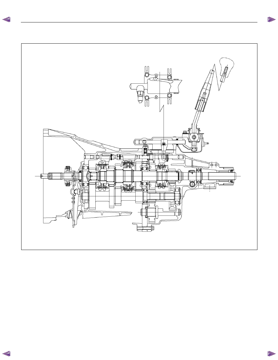
General Description
MUA5G/5H/5S Transmission (4
××××2)
A07R300006
The MUA5G/5H/5S is a constant mesh transmission,
synchronized in all speeds. The transmission has been
designed to provide low shift effort and low gear noise.
Principle parts of the transmission are the integral clutch
housing, the intermediate plate, the rear cover, and the
gears.
The transmission control box is built into the
transmission.
MANUAL TRANSMISSION 7B1-5
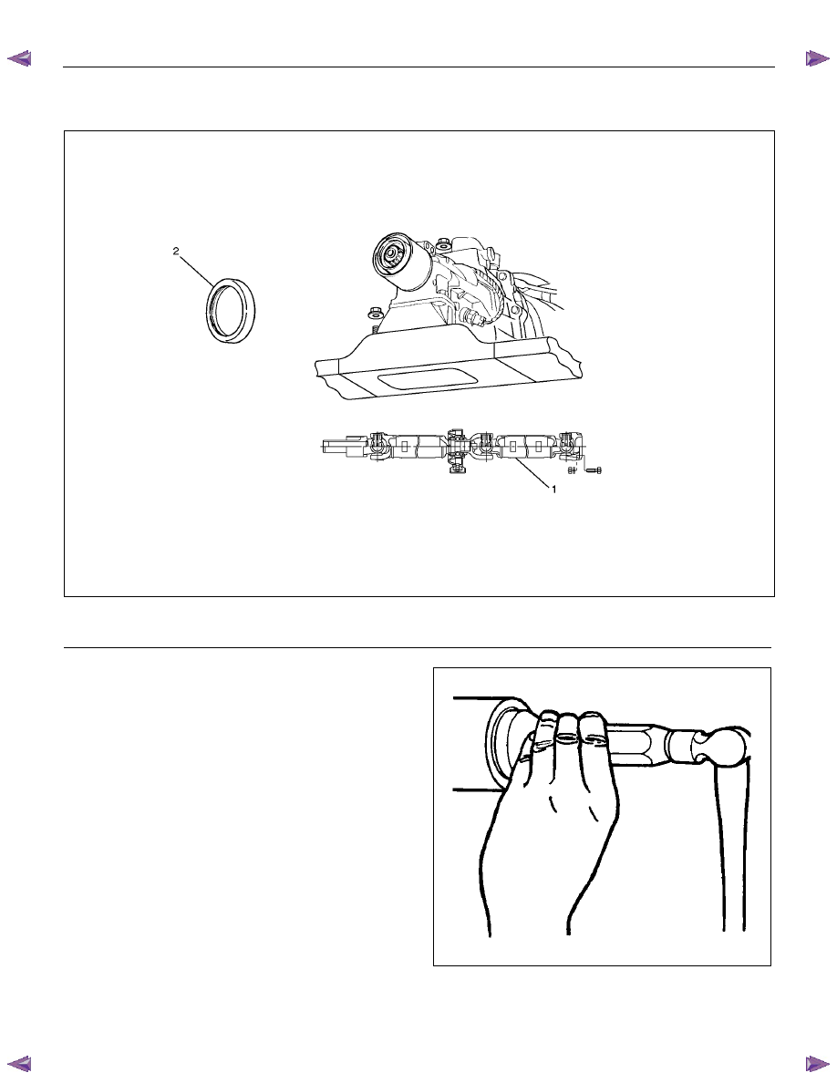
Rear Oil Seal
Disassembled View
220R300030
Legend
(1) Rear Propeller Shaft
(2) Rear Oil Seal
Removal
1. Raise and support the vehicle with suitable jack
stands.
2. Remove the propeller shaft flange yoke bolts and
nuts at the differential side.
3. Remove center bearing from the crossmember.
4. Remove prepeller shaft from the transmission main
shaft spline.
Refer to the section “Rear Propeller Shaft”.
5. Use a screwdriver to pry the rear oil seal from the
rear cover.
Installation
1. Install a new oil seal using the installer 5-8522-0050-
0.
220RS044
2.
Insert the splined yoke into the transimission
mainshaft spline.
3. Install the propeller shaft flange yoke to the drive
pinion flange.
Нет комментариевНе стесняйтесь поделиться с нами вашим ценным мнением.
Текст