Isuzu KB P190. Manual — part 797
Engine Cooling – V6 Engine
Page 6B1–53
N O T E
Should the spring clip or the O-ring seal in the
quick connect fitting be damaged during the line
removal process, then the complete fitting must
be replaced.
Reinstall
1
Remove the plugs installed in the transmission cooler
line and hose openings and wipe all exposed parts
with a clean shop rag.
•
Smear clean automatic transmission fluid on
each cooler line end, then push into the radiator
quick connect fittings. As a security check gently
pull on the connector to ensure correct
engagement.
•
As a security check, push and clip each
verification disc into place over the quick-
connect fittings. If difficulty is experienced,
repeat the installation process until the
verification disc can be clipped into place over
the radiator quick-connect fitting.
If the verifier disc does not clip into place,
the quick-connect fitting is not engaged,
rectify this before proceeding.
•
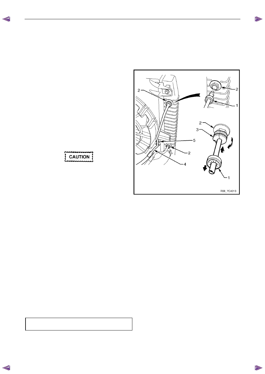
Snap the outlet cooler line (4) in the clip (5) of
the radiator fan shroud
•
At the transmission end, again clean the line
ends and proceed as detailed in step 2. As a
further security check ensure that each
verification disc can be pushed into place over
the quick connect fitting. If difficulty is
experienced, then the line has not been
completely installed. Remove and repeat the
installation process again until the verification
disc can be clipped into place over the
transmission quick connect fitting
•
Ensure that all line clamps are fitted correctly
and that the lines and hoses are correctly routed
and free of obstructions
•
Tighten the screw attaching the cooler lines
bracket to the correct torque specifications
•
If required, top up the transmission fluid level
(cold)
•
Start the engine and check for any fluid leak at
the fittings. If a leak is found, stop the engine
and rectify the leak
Figure 6B1 – 61
Transmission cooler lines bracket
attaching screw torque specification . . . . ..23.0 Nm
Engine Cooling – V6 Engine
Page 6B1–54
3.15 Radiator
Remove
Refer to 3.1 Service Notes in this Section, for
important safety items.
1
Allow engine to cool to ambient temperature (less than 50
° C), then remove coolant filler cap.
Disconnection of the battery affects certain
vehicle electronic systems. Refer to 00
Warnings, Cautions and Notes, before
removing the ground lead.
2
Disconnect the battery ground lead. Refer to 8A – Electrical Body & Chassis.
3
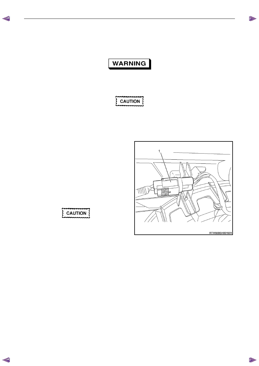
Depress the tang on the main wiring harness to the
cooling fan motor wiring harness connector (1) and
separate the connector.
4
Remove the radiator cooling fan and shroud
assembly. Refer to 3.13 Cooling Fan and Shroud
Assembly in this Section.
5
Drain the coolant from the system. Refer to 3.3
Draining and Filling Cooling System in this
Section.
Refer to ‘
‘
‘
‘ Environmental Issues ’
’
’
’ in 3.1
Service Notes, before draining the
coolant.
Figure 6B1 – 62
Engine Cooling – V6 Engine
Page 6B1–55
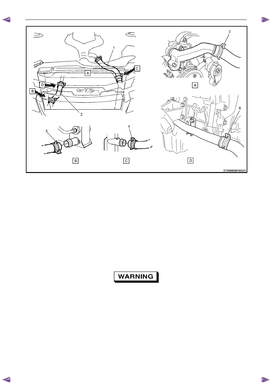
Figure 6B1 – 63
Legend
1
Radiator Hose – Upper
2
Radiator Hose – Lower
3
Hose Clamp – Upper Hose to Engine Outlet Housing
4
Hose Clamp – Upper Hose to Radiator Inlet
5
Hose Clamp – Lower Hose to Radiator Outlet
6
Hose Clamp – Lower Hose to Engine Coolant Inlet Pipe
6
Remove radiator upper hose (1) from radiator connection.
7
Remove radiator lower hose (2) from radiator connection.
8
Remove the two rubber insert mounting brackets supporting the top of the radiator.
9
Remove the two lower attaching bolts (either side) and the rubber mounts.
10
Remove the radiator from the vehicle.
Always wear protective safety glasses when
working with spring type hose clamps. Failure
to do so could result in eye injury.
Engine Cooling – V6 Engine
Page 6B1–56
Reinstall
Installation of the radiator is the reverse of removal procedures, noting the following points:
1
Before installing radiator, inspect core to ensure that there is no foreign matter in core fins. Clean out between core
fins with compressed air, blowing from rear to front.
2
If the vehicle is fitted with an automatic transmission, remove plugs from the removed cooling pipe ends and the
two quick connect fittings.
3
After wiping cooler line ends and smearing clean automatic transmission fluid over each flared line end, push into
the quick connect fitting to engage. As a security check, tug on each line to ensure correct engagement.
4
Check the transmission fluid level. Refer to the following references as required:
•
7C4 Automatic Transmission
•
4L60E On-vehicle Servicing
5
Install the following hoses:
a.
Lower radiator hose, securing with the hose clamp.
b.
Upper radiator hose, securing with the hose clamp.
6
Install the radiator cooling fan and shroud assembly. Refer to 3.13Cooling Fan and Shroud Assembly in this
Section. Ensure that electrical connectors and the transmission cooler lines are seated correctly in the integral
retainer clips before install upper radiator shroud.
7
Refill cooling system. Refer to 3.3 Draining and Filling Cooling System in this Section.
8
Check for coolant leaks. Refer to 3.7 Pressure Testing in this Section.
9
Reconnect battery ground lead. Refer to 8A Electrical Body & Chassis.
10
Check cooling fan operation. Refer to 6C1-2 Engine Management Diagnostics. Also check for correct rotational
direction of cooling fan.
Нет комментариевНе стесняйтесь поделиться с нами вашим ценным мнением.
Текст