Isuzu KB P190. Manual — part 798
Engine Cooling – V6 Engine
Page 6B1–57
Radiator Repair Procedure
Repairable Leaks
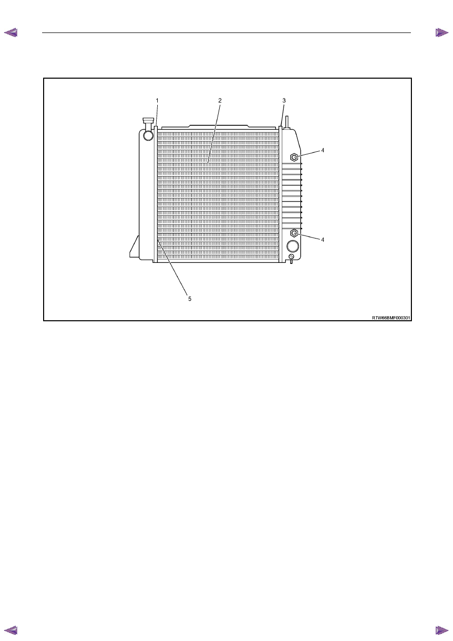
Figure 6B1 – 64
Legend:
1
Left-hand Side Tank Seal
2 Core
Tubes
3
Right-hand Side Tank Seal
4
Oil Cooler Pipe Fittings
5
Joint Between Tube and Header
There are two types of leaks that can be repaired on the aluminium-plastic radiator; core leaks and automatic
transmission oil cooler seal leaks. Leaks in the plastic tanks or the seals between the side tanks and the headers cannot
be repaired; therefore the radiator must be replaced.
Core leaks may occur in a tube or in the joints between the tubes and the headers. Seal leaks may occur in the joints
between the plastic tanks and the headers or in the joints between the oil cooler fittings and the tank (vehicles with
automatic transmission).
While some leaks can be repaired while the radiator is installed in the vehicle, it is strongly recommended that the
radiator is first removed from the vehicle.
N O T E
Minor damage to tubes, or tube to header joint
(holes up to 1
mm diameter max.) can be
repaired. Core replacement is necessary if
damage is any greater.
Engine Cooling – V6 Engine
Page 6B1–58
Repair Method
Repairs to the aluminium radiator core should only be made using the recommended 'Aluminised Silicon' based liquid
repair agent, in accordance with the recommended procedure outlined in General Core Repair in this Section. Refer to
the current Partfinder™ for Aluminised Silicon base liquid part number.
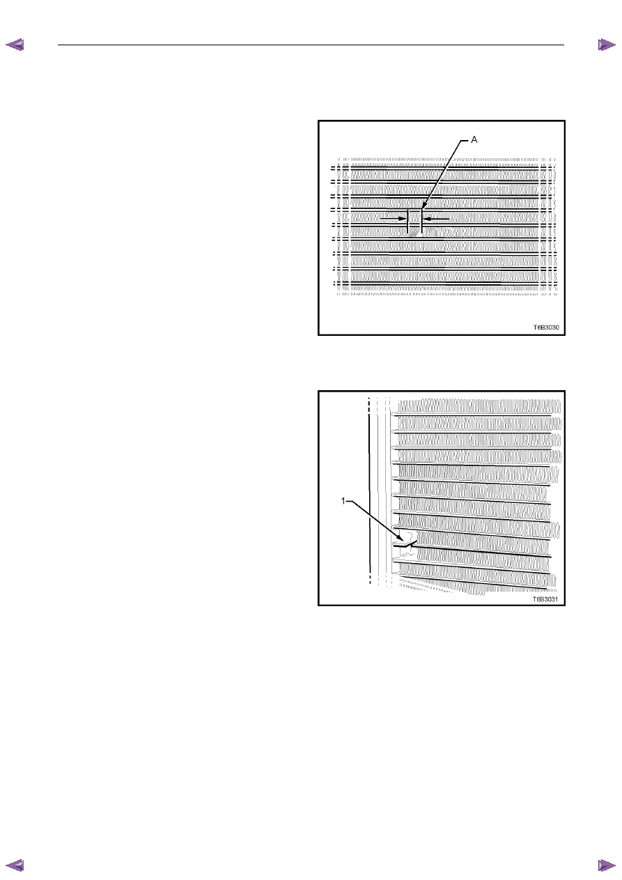
For damaged areas that are between the cooling fins, it
may be necessary to remove some of the fins. Do not
remove more fins than is necessary. Usually 6 mm
(distance ‘A’) beyond the leak or damage area, up to a
maximum of 25 mm of total fin material, is enough to
make an effective repair.
Figure 6B1 – 65
Tube Blocking
If a tube is severely damaged, it can be blocked off.
N O T E
Do not block off more than two tubes in a
radiator. Blocking off more than two tubes will
reduce the cooling capacity and efficiency of
the system and possibly result in an
overheated engine.
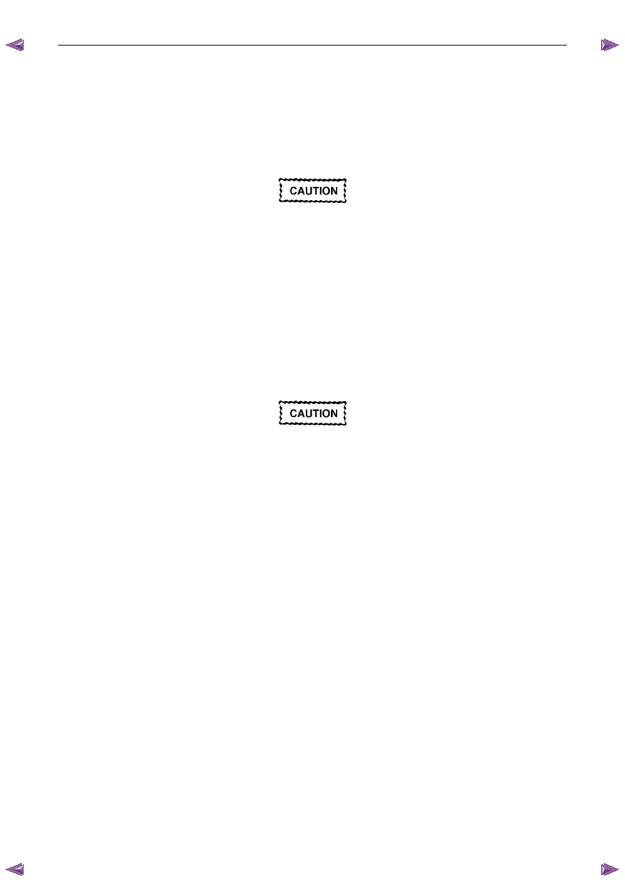
The tube should be cut off 6 mm from the header (1) and
pinched shut before it is cleaned and sealed. Refer to
General Core Repair in this Section.
Figure 6B1 – 66
Header Repair
If the header or a tube near the header requires a repair, the side tank does not have to be removed. If the repair
requires the removal of the header tank, then the radiator must be replaced.
Engine Cooling – V6 Engine
Page 6B1–59
General Core Repair
N O T E
The need for careful preparation of the surface in
the repair area cannot be over-emphasised. If the
leak area surface is not clean, the repair material
will not adhere to the surface.
Refer to ‘
‘
‘
‘ Environmental Issues ’
’
’
’ in 3.1
Service Notes, before draining the coolant.
1
Drain the coolant from the system. Refer to 3.3 Draining and Filling Cooling System in this Section.
2
Remove the radiator. Refer to 3.15
Radiator in this Section.
3
If necessary, carefully cut away fins to expose the damaged area.
N O T E
Do not cut away more than 25 mm total fin
material.
4
Clean away dirt etc. with water. Dry the affected area using hot air from a hair drier.
Do not apply flame to dry damaged area.
5
Clean affected area with petrol to remove any traces of oil.
6
Thoroughly stir contents of repair agent.
N O T E
In cases of extended shelf life, the silicon in
solution may separate from the thinner base.
Should this occur, mix contents well until agent is
again homogeneous.
7
Apply repair agent sparingly to damaged area. Do not apply an excessive amount, as this will cause blockage of
the radiator tube.
N O T E
Use a clean, dry wooden applicator to 'DRIP'
agent onto damaged area of radiator.
8
Allow radiator to stand in a clean, dry area for a minimum of 3 hours (at ambient temperature of 20 – 30
° C) with
adequate ventilation.
N O T E
Do not apply heat or flame to promote drying.
9
Reinstall the radiator. Refer to 3.15
Radiator in this Section.
Engine Cooling – V6 Engine
Page 6B1–60
Transmission Oil Cooler Leak Test
If the transmission oil cooler is suspected of leaking oil, test it before the radiator is replaced, as follows:
1
Disconnect oil cooler pipes at the flexible hose connections. Refer to 3.14 Flexible Transmission Cooler Hose, in
this Section.
2
Plug one of the connections, using a blocked pipe fitting and attach an air supply to the other flexible hose.
3
Remove coolant filler cap and check that the coolant is filled to the coolant filler cap filler neck.
4
Apply air pressure gradually, increasing up to an absolute maximum of 110 kPa. If bubbles appear in radiator neck,
the oil cooler is leaking and the radiator assembly must be replaced.
Transmission Oil Cooler Seal Replacement.
It is strongly recommended that the transmission oil cooler connector fittings to the right-hand side radiator header tank,
not be disturbed. If coolant is found to leak from either of these two areas, then the radiator should be replaced.
Нет комментариевНе стесняйтесь поделиться с нами вашим ценным мнением.
Текст