Isuzu KB P190. Manual — part 221
ENGINE MECHANICAL 6A – 79
CRANKSHAFT AND BEARING
Inspect the surface of the crankshaft journals and crankpins for
excessive wear and damage.
Inspect the oil seal fitting surfaces for excessive wear and
damage.
Inspect the oil ports for obstructions.
NOTE:
To increase crankshaft strength, tufftriding (Nitrizing
Treatment) has been applied. Because of this, it is not
possible to regrind the crankshaft surfaces.
Therefore, under size bearing are not available.
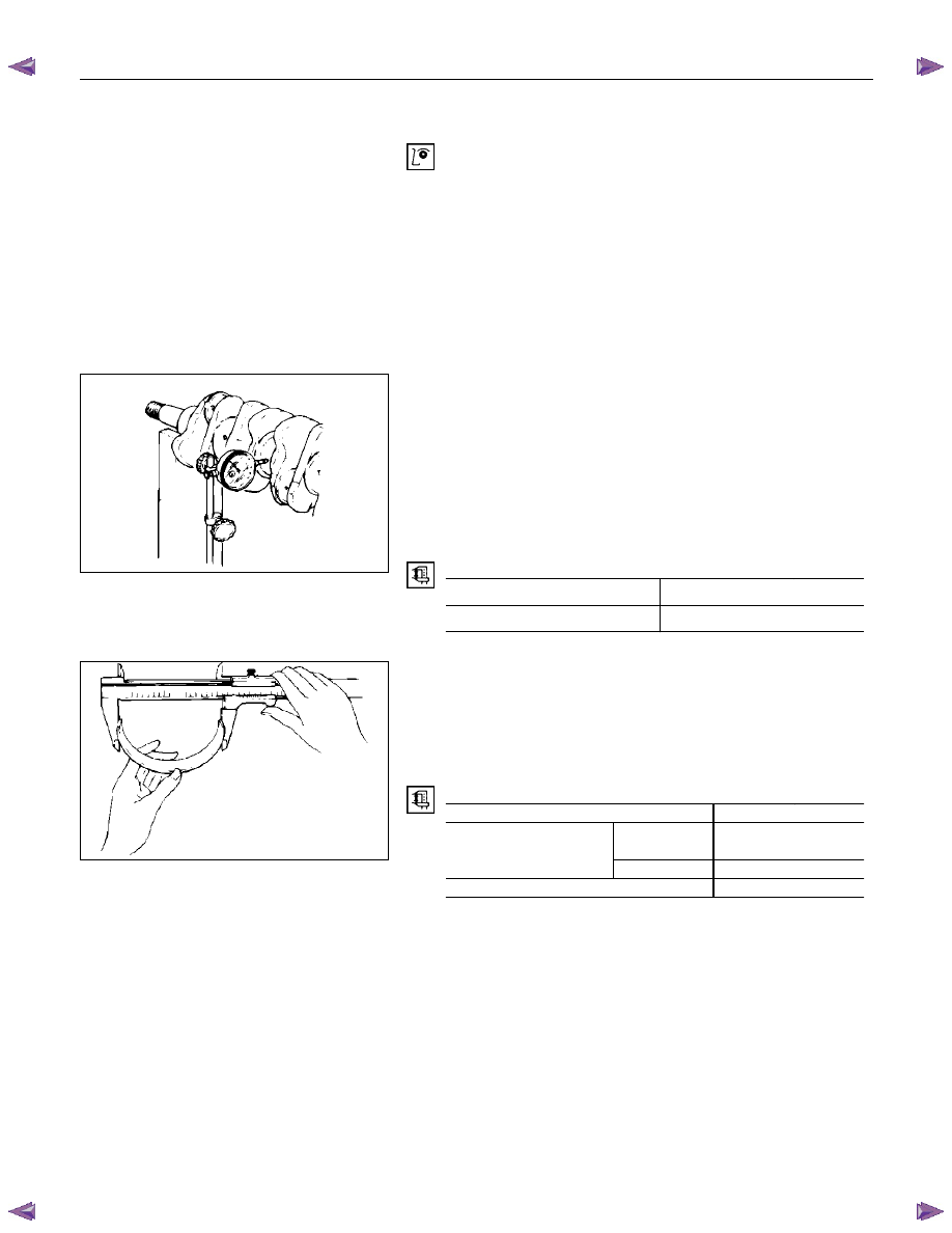
Crankshaft Run-Out
1. Set a dial indicator to the center of the crankshaft journal.
2. Gently turn the crankshaft in the normal direction of
rotation.
Read the dial indicator as you turn the crankshaft.
If the measured value exceeds the specified limit, the
crankshaft must be replaced.
Crankshaft Run-Out
mm (in)
Standard Limit
0.05 (0.002) or less
0.08 (0.003)
Bearing Spread
Use a vernier caliper to measure the bearing spread.
If the measured value is less than the specified limit, the
bearing must be replaced.
Bearing Spread
mm
(in)
Limit
4JA1T (L),
4JA1TC
64.5 (2.54)
Creankshaft Bearing
4JH1TC 74.5
(2.93)
Connecting Rod Bearing
56.5 (2.22)
015LX061
015RY00007
6A – 80 ENGINE MECHANICAL
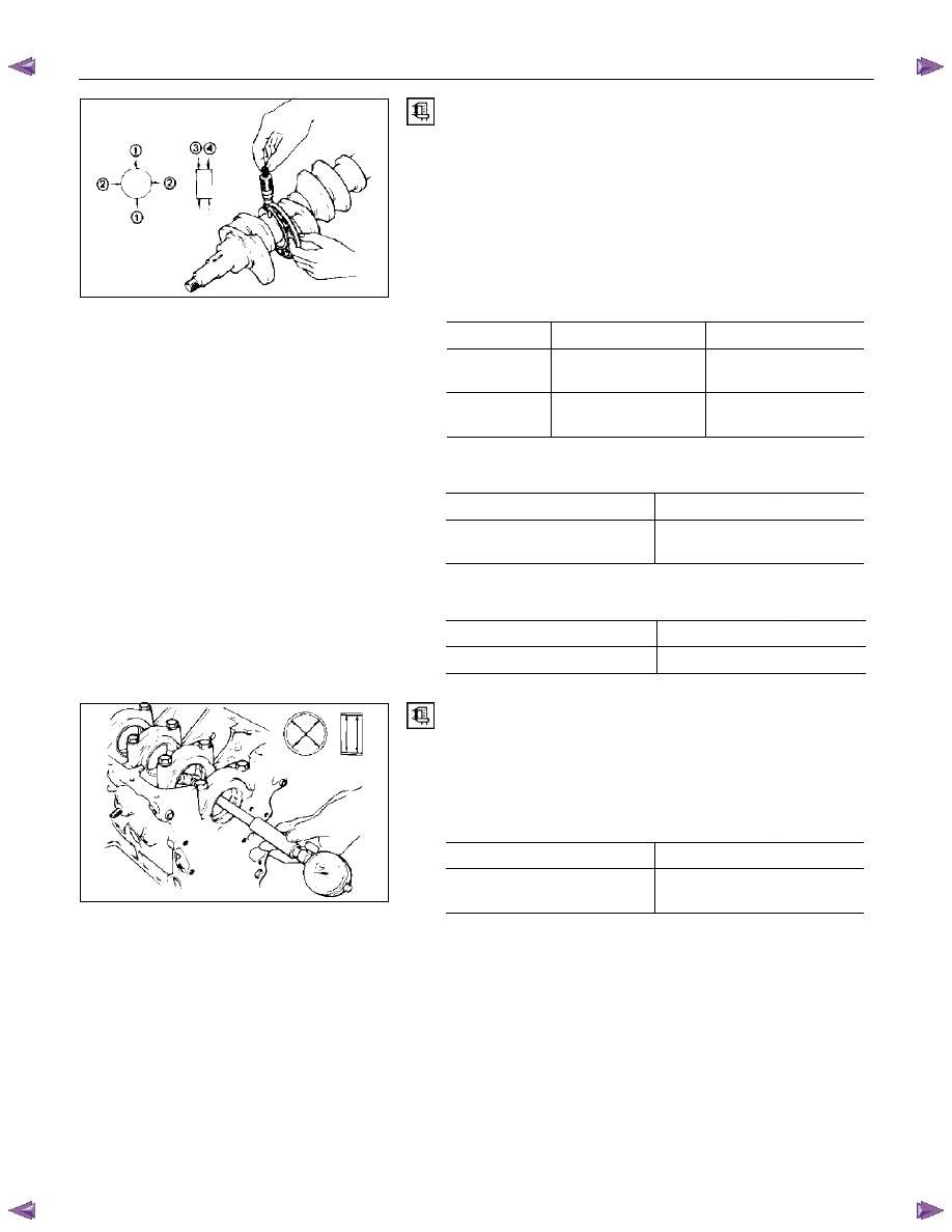
Crankshaft Journal and Crankpin Diameter
1. Use a micrometer to measure the crankshaft journal
diameter across points 1 - 1 and 2 - 2.
2. Use the micrometer to measure the crankshaft journal
diameter at the two points (3 and 4).
3. Repeat Steps 1 and 2 to measure the crankpin diameter.
If the measured values are less than the specified limit, the
crankshaft must be replaced.
Crankshaft Journal and Diameter
mm (in)
Standard
Limit
4JA1T (L),
4JA1TC
59.921-59.928
(2.3591-2.3594)
59.91 (2.3586)
4JH1TC
69.917-69.932
(2.7526-2.7532)
69.91(2.7524)
Crankpin Diameter
mm
(in)
Standard
Limit
52.915 - 52.930
(2.0833 - 2.0839)
52.90 (2.083)
Crankshaft Journal and Crankpin Uneven Wear
mm
(in)
Standard
Limit
0.05 (0.002) or less
0.08 (0.003)
Crankshaft Journal and Crankpin Diameter
If the clearance between the measured bearing inside diameter
and the crankshaft journal diameter exceeds the specified limit,
the bearing and/or the crankshaft must be replaced.
Crankshaft Journal and Bearing Clearance
mm (in)
Standard
Limit
0.032 - 0.077
(0.0013 - 0.0030)
0.110 (0.0043)
015RY00008
015RY00009
ENGINE MECHANICAL 6A – 81
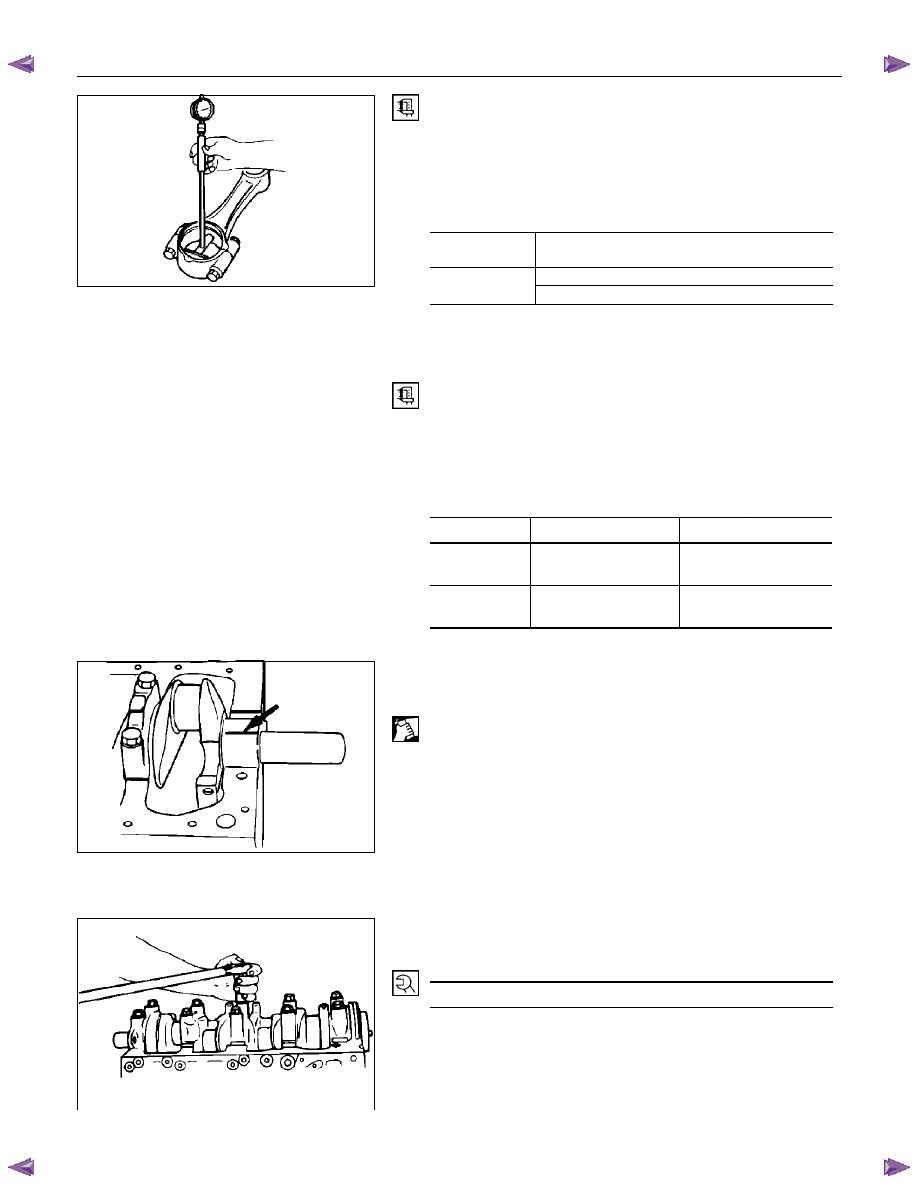
Connecting Rod Bearing Inside Diameter
1. Install the bearing to the connecting rod big end.
2. Tighten the bearing cap to the two step of anglar tightening
method.
Connecting Rod Bearing Cap Bolt Torque
N·m (kg·m/Ib ft)
4JA1T (L),
4JA1TC
78-88 (8.0/57 – 9.0/65)
1st step ; 29.0–29.2 (3.00/22.0–3.01/22.2)
4JH1TC
2nd step ; 45
°
-60
°
3. Use an inside dial indicator to measure the connecting rod
bearing inside diameter.
Crankpin and Bearing Clearance
If the clearance between the measured bearing inside diameter
and the crankpin exceeds the specified limit, the bearing
and/or the crankshaft must be replaced.
Crankpin and Bearing Clearance
mm (in)
Standard
Limit
4JA1T (L),
4JA1TC
0.029-0.066
(0.0011-0.0026)
0.100(0.0039)
4JH1TC
0.029-0.083
(0.0011-0.033)
0.100 (0.0039)
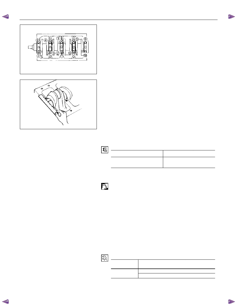
Clearance Measurements (With Plastigage)
Crankshaft Journal and Bearing Clearance
1. Clean the cylinder body, the journal bearing fitting surface,
the bearing caps, and the bearings.
2. Install the bearings to the cylinder body.
3. Carefully place the crankshaft on the bearings.
4. Rotate the crankshaft approximately 30
°
to seat the
bearing.
5. Place the Plastigage (arrow) over the crankshaft journal
across the full width of the bearing.
6. Install the bearing caps with the bearing.
7. Tighten the bearing caps to the specified torque.
Crankshaft Bearing Cap Bolt Torque
mm (in)
167 (17/123)
Do not allow the crankshaft to turn during bearing cap
installation and tightening.
8. Remove the bearing cap.
015RY00012
015RY00013
015RY00011
6A – 82 ENGINE MECHANICAL
9. Compare the width of the Plastigage attached to either the
crankshaft or the bearing against the scale printed on the
Plastigage container.
If the measured value exceeds the limit, perform the
following additional steps.
1. Use a micrometer to measure the crankshaft outside
diameter.
2. Use an inside dial indicator to measure the bearing
inside diameter.
If the crankshaft journal and bearing clearance
exceeds the limit, the crankshaft and/or the bearing
must be replaced.
Crankshaft Journal and Bearing Clearance
mm (in)
Standard
Limit
0.032 - 0.077
(0.0013 - 0.0030)
0.110 (0.0043)
Crankpin and Bearing Clearance
1. Clean the crankshaft, the connecting rod, the bearing cap,
and the bearings.
2. Install the bearing to the connecting rod and the bearing
cap.
Do not allow the crankshaft to move when installing the
bearing cap.
3. Prevent the connecting rod from moving.
4. Attach the Plastigage to the crankpin.
Apply engine oil to the Plastigage to keep it from falling.
5. Install the bearing cap and tighten it to the two step of
anglar tihtening method.
Do not allow the connecting rod to move when installing
and tightening the bearing cap.
Connecting Rod Bearing Cap Bolt Torque
N·m (kg·m/Ib ft)
4JA1T (L),
4JA1TC
78-88 (8.0/57 – 9.0/65)
1st step ; 29.0–29.2 (3.00/22.0–3.01/22.2)
4JH1TC
2nd step ; 45
°
-60
°
015LX129
015LX060
Нет комментариевНе стесняйтесь поделиться с нами вашим ценным мнением.
Текст