Isuzu KB P190. Manual — part 222
ENGINE MECHANICAL 6A – 83
6. Remove the bearing cap.
7. Compare the width of the Plastigage attached to either the
crankshaft or the bearing against the scale printed on the
Plastigage container.
If the measured value exceeds the specified limit, perform
the following additional steps.
1. Use a micrometer to measure the crankpin outside
diameter.
2. Use an inside dial indicator to measure the bearing
inside diameter.
If the crank pin and bearing clearance exceeds the
specified limit, the crankshaft and/or the bearing must
be replaced.
Crankpin and Bearing Clearance
mm (in)
Standard
Limit
4JA1T (L),
4JA1TC
0.029-0.066
(0.0011-0.0026)
0.100 (0.0039)
4JH1TC
0.029-0.083
(0.0011-0.0033)
0.100 (0.0039)
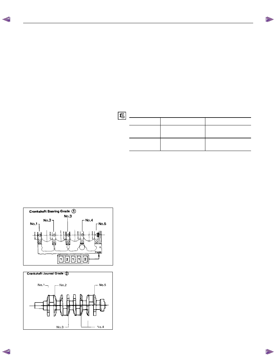
CRANKSHAFT BEARING SELECTION
Crankshaft bearing selection is based on the measured
diameters of the crankshaft journals and the bearing inserts.
Match the crankshaft bearing housing grade marks and the
crankshaft journal grade marks in the table below to determine
the correct crankshaft bearing size.
Crankshaft Bearing Housing Grade Mark
Position
Crankshaft bearing housing grade marks 1, 2 or 3 are stamped
on the rear right hand side of the cylinder body.
Crankshaft Journal Grade Mark Position
The crankshaft journal grade marks (1 or -, 2 or --, 3 or ---) are
stamped on each crankshaft journal web.
The crankshaft journal and bearing clearance must be the
same for each position after installation of the crankshaft and
the crankshaft bearings.
NOTE:
The crankshaft journal mark No. 4 is stamped on
crankshaft No. 4 journal web front side or rear side.
015LX060
015RY00016
6A – 84 ENGINE MECHANICAL
015RY00017
RTW46ASH002501
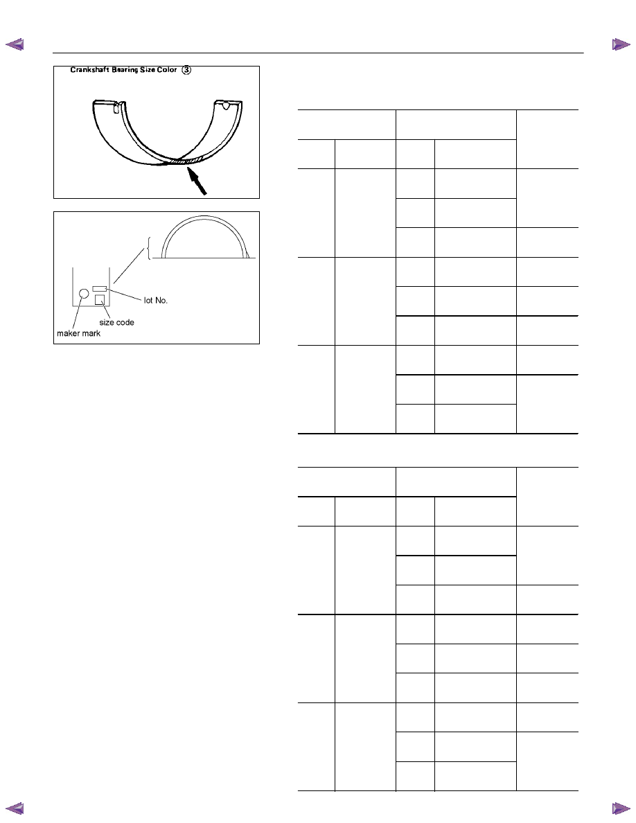
REFERENCE
4JA1T(L), 4JA1TC
mm (in)
Crankshaft
Bearing Housing
Crankshaft Journal
Grade
Mark
Diamaeter
Grade
Mark
Diamaeter
Crankshaft
Bearing
Size Code
1 or
-
59.927-59.932
(2.3593-23.595)
2 or
- -
59.922-59.927
(2.3591-2.3539)
Brown or 4
1
63.992-
64.000
(2.5194-
2.5197)
3 or
- - -
59.917-59.922
(2.3589-2.3591)
Yellow or 5
1 or
-
59.927-59.932
(2.3593-2.3595)
Black or 2
2 or
- -
59.922-59.927
(2.3591-2.3593)
Blue or 3
2
63.983-
63.992
(2.5190-
2.5194)
3 or
- - -
59.917-59.922
(2.3589-2.3591)
Brown or 4
1 or
-
59.927-59.932
(2.3593-2.3595)
Green or 1
2 or
- -
59.922-59.927
(2.3591-2.3593)
3
63.975-
63.983
(2.5187-
2.5190)
3 or
- - -
59.917-59.922
(2.3598-2.3591)
Black or 2
4JH1TC mm
(in)
Crankshaft
Bearing Housing
Crankshaft Journal
Grade
Mark
Diamaeter
Grade
Mark
Diamaeter
Crankshaft
Bearing
Size Code
1 or
-
69.927-69.932
(2.7530-2.7532)
2 or
- -
69.922-69.927
(2.7528-2.7530)
4
1
73.992-
74.000
(2.9131-
2.9134)
3 or
- - -
69.917-69.922
(2.7556-2.7528)
5
1 or
-
69.927-69.932
(2.7530-2.7532)
2
2 or
- -
69.922-69.927
(2.7528-2.7530)
3
2
73.983-
73.992
(2.9127-
2.9131)
3 or
- - -
69.917-69.922
(2.7556-2.7528)
4
1 or
-
69.927-69.932
(2.7530-2.7532)
1
2 or
- -
69.922-69.927
(2.7528-2.7530)
3
73.975-
73.983
(2.9124-
2.9127)
3 or
- - -
69.917-69.922
(2.7526-2.7528)
2
ENGINE MECHANICAL 6A – 85
CRANKSHAFT PILOT BEARING
Check the crankshaft pilot bearing for excessive wear and
damage and replace it if necessary.
Crankshaft Pilot Bearing Replacement
Crankshaft Pilot Bearing Removal
Use the pilot bearing remover to remove the crankshaft pilot
bearing.
Pilot Bearing Remover: 5-8840-2000-0
Sliding Hammer: 5-8840-0019-0
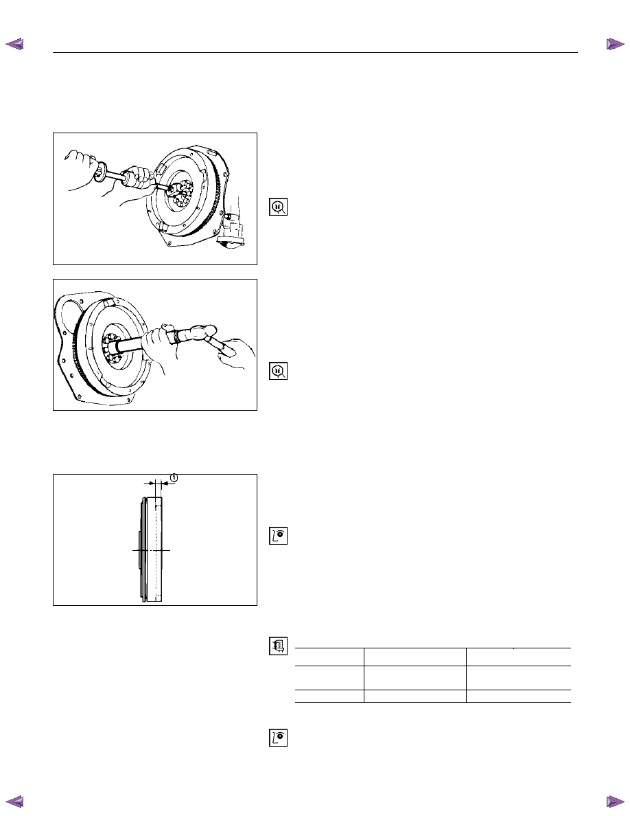
Crankshaft Pilot Bearing Installation
1. Place the crankshaft pilot bearing right angle across the
crankshaft bearing installation hole.
2. Tap around the edges of the crankshaft pilot bearing outer
races with a brass hammer to drive the bearing into the
crankshaft bearing installation hole.
Pilot Bearing Installer: 5-8522-0024-0
NOTE:
Strike only the crankshaft pilot bearing outer race with
the hammer. Do not strike the bearing inner race.
Bearing damage and reduced bearing service life will
result.
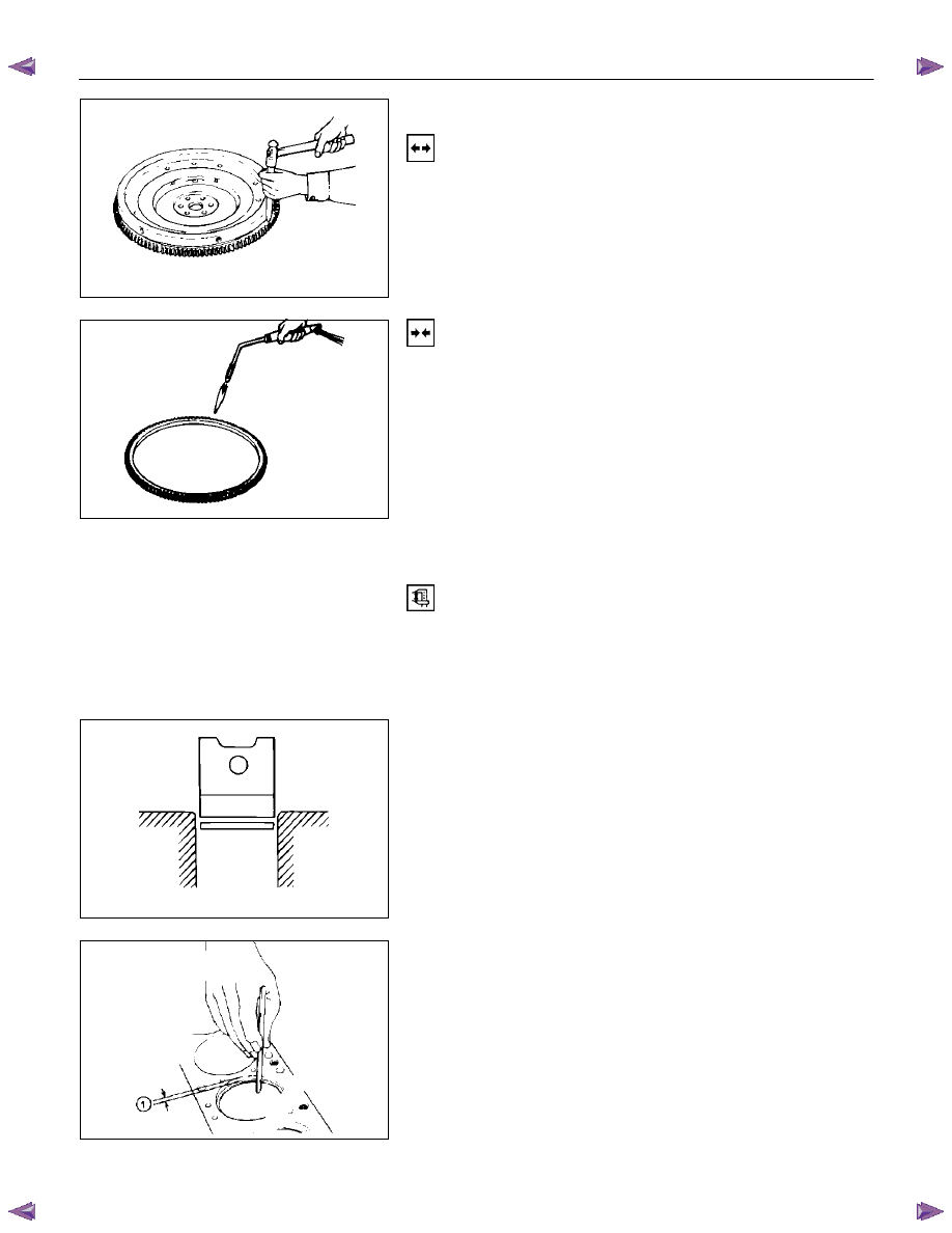
FLYWHEEL AND RING GEAR
Flywheel
1. Inspect the flywheel friction surface for excessive wear and
heat cracks.
2. Measure the flywheel friction surface depth.
If the measured value is within the specified limit, the
flywheel may be reground.
If the measured value exceeds the specified limit, the
flywheel must be replaced.
Flywheel Friction Surface Depth (1)
mm (in)
Standard
Limit
4JA1T (L),
4JA1TC
20 (0.7874)
21 (0.8267)
4JH1TC
18 (0.7087)
19 (0.7480)
Ring Gear
Inspect the ring gear.
If the ring gear teeth are broken or excessively worn, the ring
gear must be replaced.
015RY00010
015RY00019
015RY00018
6A – 86 ENGINE MECHANICAL
Ring Gear Replacement
Ring Gear Removal
Strike around the edges of the ring gear with a hammer and
chisel to remove it.
Ring Gear Installation
1. Heat the ring gear evenly with a gas burner to invite
thermal expansion.
Do not allow the temperature of the gas burner to exceed
200
°
C (390
°
F).
2. Install the ring gear when it is sufficiently heated.
The ring gear must be installed with the chamfer facing the
clutch.
PISTON
Piston Grade Selection and Cylinder Bore
Measurement
Refer to the Section "Cylinder Body", Item "Cylinder Liner Bore
Measurement" for details on piston grade selection and
cylinder liner bore measurement.
Piston Ring Gap
1. Insert the piston ring horizontally (in the position it would
assume if it were installed to the piston) into the cylinder
liner.
2. Push the piston ring into the cylinder bore until it reaches
the measuring point 1 or 2 where the cylinder liner bore is
the smallest.
Do not allow the piston ring to slant to one side or the
other. It must be perfectly horizontal.
Measuring Point 1 10 mm (0.4 in)
or
Measuring Point 2 120 mm (4.7 in)
020LX008
020LX009
015LX023
015RY00020
Нет комментариевНе стесняйтесь поделиться с нами вашим ценным мнением.
Текст