Isuzu KB P190. Manual — part 415
ENGINE CONTROL SYSTEM (4JK1/4JJ1) 6E-43
Diagnostic Information and Procedures
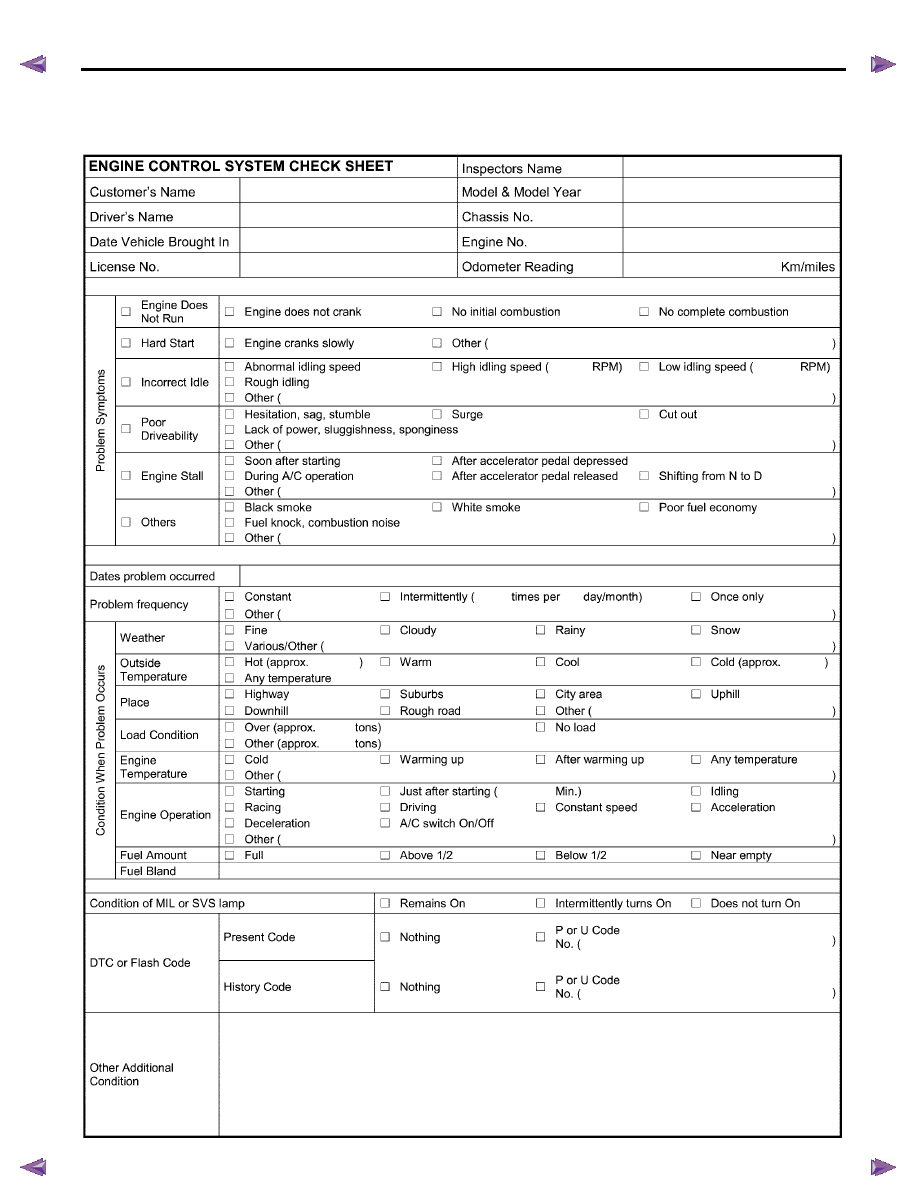
Engine Control System Check Sheet
6E-44 ENGINE CONTROL SYSTEM (4JK1/4JJ1)
Diagnostic Starting Point - Engine Controls
Begin the system diagnosis with Diagnostic System
Check - Engine Controls. The Diagnostic System
Check - Engine Controls will provide the following
information:
• The identification of the control modules which
command the system.
• The ability of the control modules to communicate
through the serial data circuit.
• The identification of any stored diagnostic trouble
codes (DTCs) and the their statuses.
The use of the Diagnostic System Check - Engine
Controls will identify the correct procedure for
diagnosing the system and where the procedure is
located.
Important: Engine Control System Check Sheet must
be used to verify the complaint vehicle, you need to
know the correct (normal) operating behavior of the
system and verify that the customer complaint is a valid
failure of the system.
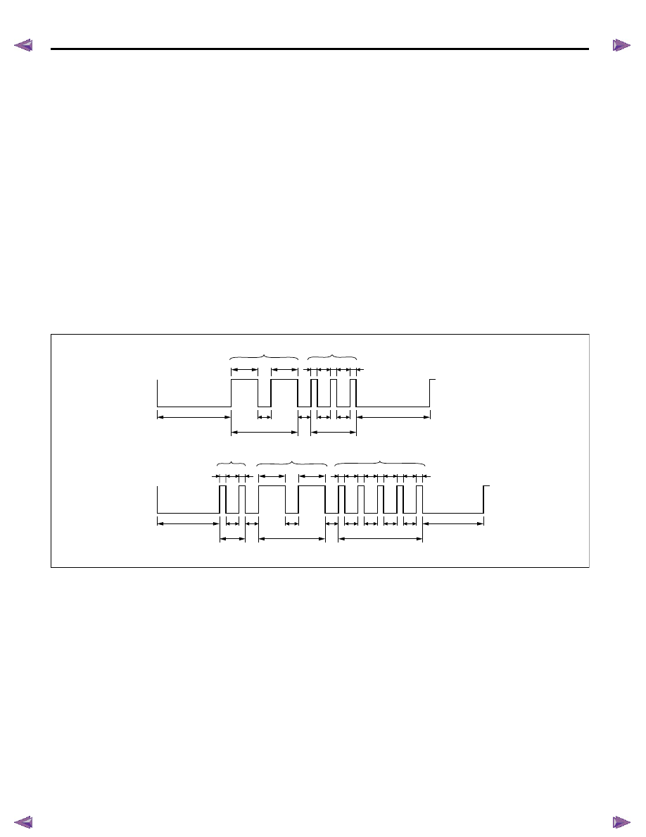
Reading Flash Diagnostic Trouble Codes (DTC)
The provision for communicating with the ECM is the
Data Link Connector (DLC). The DTC(s) stored in the
ECM memory can be read either through a hand-held
diagnostic scanner such as Tech 2 plugged into the
DLC or by counting the number of flashes of the
malfunction indicator lamp (MIL) or the service vehicle
soon (SVS) lamp when the diagnostic test terminal of
the DLC is grounded. The DLC terminal "1" (diagnostic
request) is pulled "Low" (grounded) by jumped to DLC
terminal "4", which is a ground wire. Once terminals "1"
and "4" have been connected, turn the ignition switch
ON, with the engine OFF. The MIL (except Euro 4
specification) or the SVS lamp (Euro 4 specification)
will indicate a DTC three times is a DTC is present and
history. If more than one DTC has been stored in the
ECM's memory, the DTCs will be output set order with
each DTC being displayed three times. The flash DTC
display will continue as long as the DLC is shorted.
RTW76ESF000301
ON
OFF
ON
OFF
1.2
3.2
2.6
2.6
2nd digit number
1st digit number
3.2
0.6
2
1.2
0.6
0.6
0.6
0.3
0.3
0.3
0.3
0.3
0.3
0.3
0.3
Example:DTC 23 stored
Unit: Second
Example:DTC 225 stored
3rd digit
number
2nd digit number
1st digit number
0.6
0.6
0.6
0.6
0.6
0.6
0.6
0.6
3
0.3
0.3
1.2
1.2
2
2
5

ENGINE CONTROL SYSTEM (4JK1/4JJ1) 6E-45
Diagnostic System Check - Engine Controls
Description
The Diagnostic System Check - Engine Controls is an
organized approach to identifying a condition that is
created by a malfunction in the electronic engine
control system. The Diagnostic System Check must be
the starting point for any driveability concern. The
Diagnostic System Check directs the service technician
to the next logical step in order to diagnose the
concern. Understanding and correctly using the
diagnostic table reduces diagnostic time, and prevents
the replacement of good parts.
Test Description
The numbers below refer to the step numbers on the
diagnostic table.
2. Lack of communication may be because of a partial
or a total malfunction of the serial data circuit.
7. The presence of DTCs which begin with U, indicate
that some other module is not communicating.
10. If there are other modules with DTCs set, refer to
the DTC list. The DTC list directs you to the appropriate
diagnostic procedure. If the control module stores
multiple DTCs, diagnose the DTCs in the following
order:
• Component level DTCs, such as sensor DTCs,
solenoid DTCs, actuator DTCs, and relay DTCs.
Diagnose the multiple DTCs within this category in
numerical order. Begin with the lowest numbered
DTC, unless the diagnostic table directs you
otherwise.
Diagnostic System Check Engine Controls
Important:
• DO NOT perform this diagnostic if there is not a
driveability concern, unless another procedure
directs you to this diagnostic.
• Before you proceed with diagnosis, search for
applicable service bulletins.
• Unless a diagnostic procedure instructs you, DO
NOT clear the DTCs.
• If there is a condition with the starting system, refer
to the starting system section in the engine
mechanical.
• Ensure the battery has a full charge.
• Ensure the battery cables (+) (-) are clean and
tight.
• Ensure the ECM grounds are clean, tight, and in
the correct location.
• Ensure the ECM harness connectors are clean
and correctly connected. DO NOT attempt to
crank the engine with ECM harness connectors
disconnect.
• Ensure the ECM terminals are clean and correctly
mating.
• Ensure the fuel injector ID code data is correctly
programmed in to the ECM.
• Ensure the immobilizer security information is
correctly programmed into the ECM and
immobilizer control unit (ICU).
• If there are fuel system DTC’s (P0087, P0088,
P0089, P0093, P1093 or P1094), diagnose sensor
DTCs, solenoid DTCs, actuator DTCs and relay
DTCs first.
Diagnostic System Check - Engine Controls
Step
Action
Value(s)
Yes
No
1
Install a scan tool.
Does the scan tool turn ON?
—
Go to Step 2
Go to Scan Tool
Does Not Power Up
2
1.
Turn ON the ignition, with the engine OFF.
2.
Attempt to establish communication with the
listed control modules.
• ECM
• Immobilizer control unit (ICU) (If so
equipped)
• Transmission control module (TCM)
(AISIN A/T only)
Does the scan tool communicate with all the listed
control modules?
—
Go to Step 3
Go to Scan Tool
Does Not
Communicate with
CAN Device

6E-46 ENGINE CONTROL SYSTEM (4JK1/4JJ1)
3
Notice: If an immobilizer system is active the ECM
will disable the fuel injection causing the engine to
stall immediately after starting and energize the
starter cut relay to disable cranking.
Attempt to crank the engine.
Does the engine crank?
—
Go to Step 4
Go to Step 5
4
Attempt to start the engine.
Does the engine start and idle?
—
Go to Step 6
Go to Engine
Cranks but Does
Not Run
5
Does the scan tool display ECM DTCs P0615,
P0633, P161B or U0167?
—
Go to Applicable
DTC
Problem is relating
to starting system.
Refer to the
applicable
diagnostic chart in
starting system
6
Select the DTC display function for the following
control modules:
• ECM
• ICU (If so equipped)
• TCM (AISIN A/T only)
Does the scan tool display any DTCs?
—
Go to Step 7
Go to Step 11
7
Does the scan tool display DTCs which begin with
U or other control module communication fault
DTCs?
—
Go to Applicable
DTC
Go to Step 8
8
Does the scan tool display ECM DTCs P0601,
P0602, P0604, P0606 or P1621?
—
Go to Applicable
DTC
Go to Step 9
9
Does the scan tool display ECM DTCs P0562 or
P0563, P156A or P156B?
—
Go to Applicable
DTC
Go to Step 10
10
Is there any other code in any controller that has
not been diagnosed?
—
Go to Applicable
DTC
Go to Step 11
11
Is the customer’s concern with the automatic
transmission?
—
Go to Diagnostic
System Check -
Transmission
Controls
Go to Step 12
12
Is the customer’s concern with the immobilizer
system?
—
Go to Diagnostic
System Check -
Immobilizer
Controls
Go to Step 13
13
1.
Review the following symptoms.
2.
Refer to the applicable symptom diagnostic
table:
• Hard Start
• Rough, Unstable, or Incorrect Idle and
Stalling
• High Idle Speed
• Cuts Out
• Surges
• Lack of Power, Sluggishness, or
Sponginess
• Hesitation, Sag, Stumble
• Abnormal Combustion Noise
• Poor Fuel Economy
• Excessive Smoke (Black Smoke)
• Excessive Smoke (White Smoke)
Did you find and correct the condition?
—
System OK
Go to Intermittent
Conditions
Step
Action
Value(s)
Yes
No
Нет комментариевНе стесняйтесь поделиться с нами вашим ценным мнением.
Текст