Isuzu KB P190. Manual — part 416
ENGINE CONTROL SYSTEM (4JK1/4JJ1) 6E-47
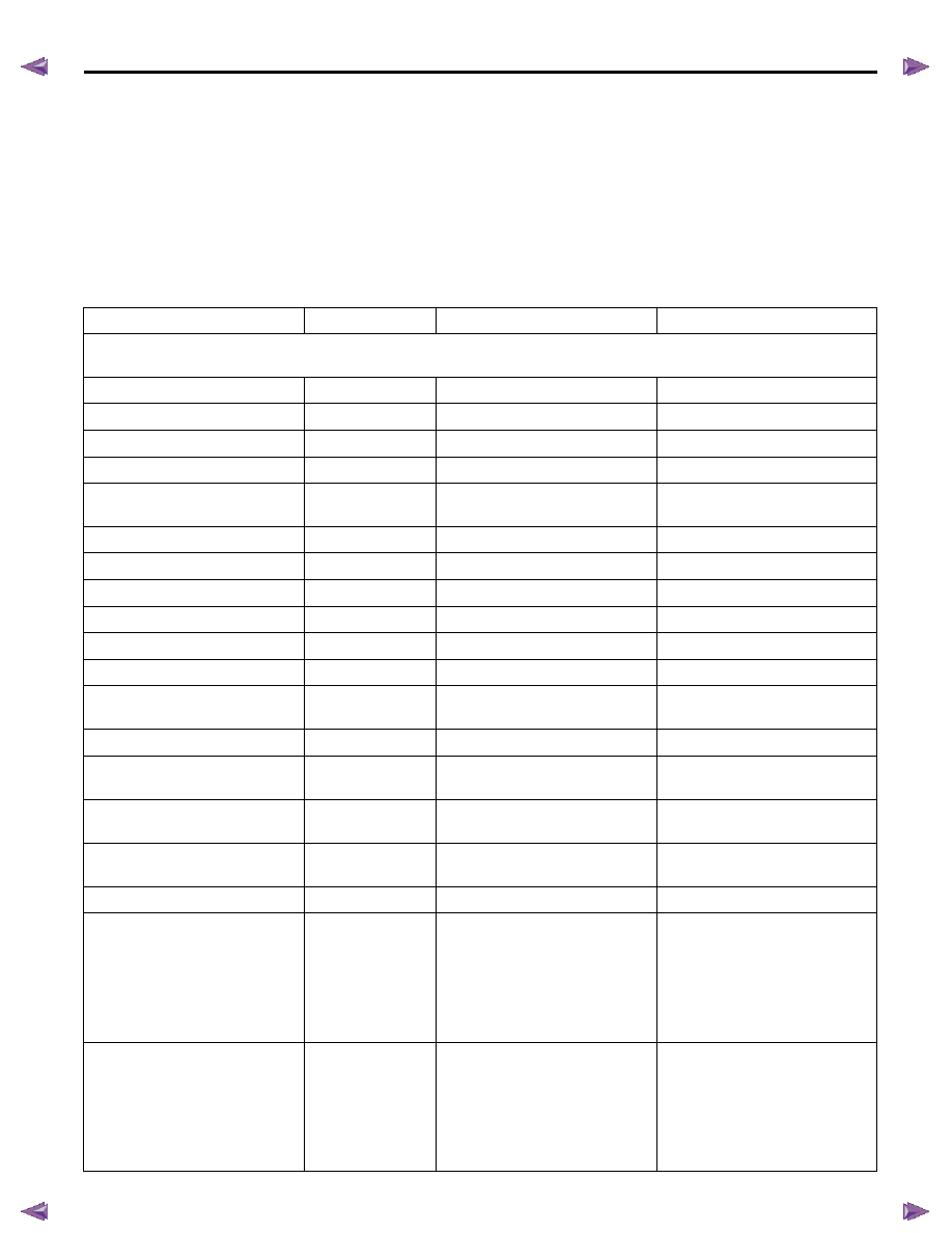
Scan Tool Data List
The Engine Scan Tool Data List contains all engine
related parameters that are available on the scan tool.
A given parameter may appear in any one of the data
lists, and in some cases may appear more than once,
or in more than one data list in order to group certain
related parameters together. Use the Engine Scan Tool
Data List only after the following is determined:
• The Engine Controls - Diagnostic System Check is
completed.
• On-board diagnostics are functioning properly.
Scan tool values from a properly running engine may
be used for comparison with the engine you are
diagnosing. The Engine Scan Tool Data List represents
values that would be seen on a normal running engine.
Only the parameters listed below are referenced in this
service manual for use in diagnosis.
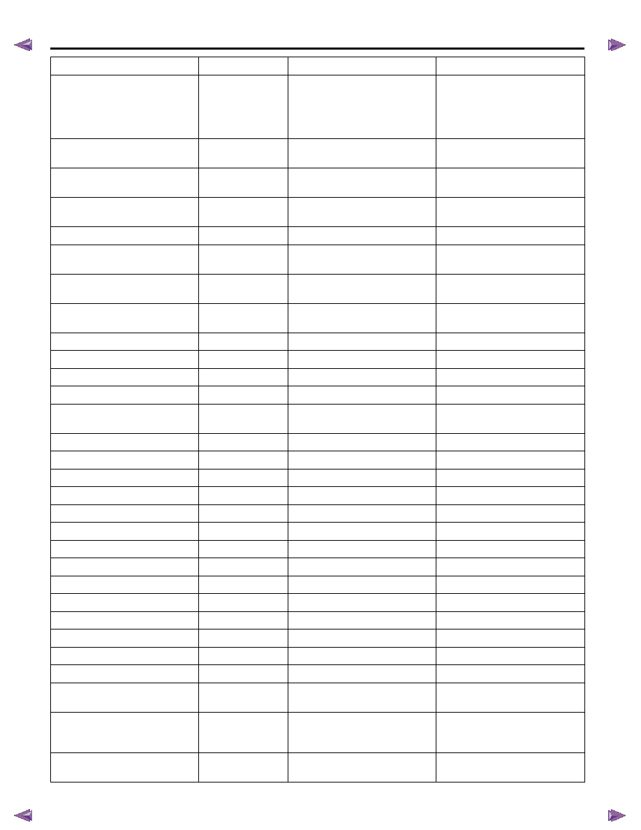
Scan Tool Parameter
Units Displayed
Typical Data Value at Engine Idle
Typical Data Value at 2000RPM
Operating Conditions: Engine idling or 2000RPM/ Engine coolant temperature is between 75 to 85
°C (167 to 185°F)/
Accelerator pedal is constant/ Neutral or Park/ Accessories OFF/ Vehicle located at sea level
Engine Speed
RPM
Nearly 700 RPM
Nearly 2000 RPM
Desired Engine Idle Speed
RPM
700 RPM
700 RPM
Calculated Engine Load
%
-
-
Coolant Temperature
°C/ °F
75 to 85
°C/ 167 to 185°F
75 to 85
°C/ 167 to 185°F
Engine Coolant Temperature
Sensor
Volts
0.4 to 0.6 volts
0.4 to 0.6 volts
Intake Air Temperature
°C/ °F
20 to 40
°C/ 68 to 104 °F
20 to 40
°C/ 68 to 104 °F
Intake Air Temperature Sensor
Volts
1.4 to 2.3 volts
1.4 to 2.3 volts
Fuel Temperature
°C/ °F
20 to 60
°C/ 68 to 140 °F
20 to 60
°C/ 68 to 140 °F
Fuel Temperature Sensor
Volts
0.8 to 2.3 volts
0.8 to 2.3 volts
MAF (Mass Air Flow)
g/sec
300 to 600 g/sec
200 to 600 g/sec
MAF Sensor (Mass Air Flow)
Volts
1.2 to 1.6 volts
2.0 to 2.7 volts
Barometric Pressure
kPa/psi
Nearly 100 kPa/ 14.5 psi at sea
level
Nearly 100 kPa/ 14.5 psi at sea
level
Barometric Pressure Sensor
Volts
Nearly 2.3 volts at sea level
Nearly 2.3 volts at sea level
Turbocharger Solenoid
Command
%
50 to 60 %
50 to 60 %
Desired Boost Pressure
kPa/ psi
Nearly 100 kPa/ 14.5 psi at sea
level
Less than 120 kPa/ 17.4 psi
Boost Pressure
kPa/ psi
Nearly 100 kPa/ 14.5 psi at sea
level
Less than 120 kPa/ 17.4 psi
Boost Pressure Sensor
Volts
Nearly 1.0 volt
Less than 1.3 volts
Desired Fuel Rail Pressure
MPa/ psi
30 MPa/ 4,350 psi
More than 70 MPa/ 10,200 psi
(4JJ1 Euro 4 specification)
More than 50 MPa/ 7,250 psi
(4JJ1 except Euro 4
specification)
More than 60 MPa/ 8,700 psi
(4JK1)
Fuel Rail Pressure
MPa/ psi
27 to 33 MPa/ 3,900 to 4,800 psi
More than 70 MPa/ 10,200 psi
(4JJ1 Euro 4 specification)
More than 50 MPa/ 7,250 psi
(4JJ1 except Euro 4
specification)
More than 60 MPa/ 8,700 psi
(4JK1)
6E-48 ENGINE CONTROL SYSTEM (4JK1/4JJ1)
Fuel Rail Pressure Sensor
Volts
1.4 to 1.5 volts
More than 2.1 volts (4JJ1 Euro 4
specification)
More than 1.8 volts (4JJ1 except
Euro 4 specification)
More than 1.9 volts (4JK1)
FRP Regulator Command (Fuel
Rail Pressure)
%
35 to 50 %
35 to 45 %
FRP Regulator Commanded Fuel
Flow
mm
3
/sec
More than 1,000 mm
3
/sec
More than 2,000 mm
3
/sec
FRP Regulator Feedback (Fuel
Rail Pressure)
mA
1,600 to 2,000 mA
1,500 to 1,800 mA
Accelerator Pedal Position
%
0%
10 to 25 %
APP Sensor 1 (Accelerator Pedal
Position)
Volts
0.2 to 1.0 volts
1.0 to 1.7 volts
APP Sensor 2 (Accelerator Pedal
Position)
Volts
3.8 to 4.6 volts
3.3 to 3.9 volts
APP Sensor 3 (Accelerator Pedal
Position)
Volts
3.8 to 4.6 volts
3.7 to 4.0 volts
EGR Solenoid Command
%
Less than 30 %
Less than 30 %
Desired EGR Position
%
Less than 70 %
Less than 80 %
EGR Position
%
Less than 70 %
Less than 80 %
EGR Position Sensor
Volts
Less than 2.9 volts
Less than 3.1 volts
Intake Throttle Solenoid
Command
%
Less than 30 %
Less than 40 %
Desired Intake Throttle Position
%
Less than 30 %
Less than 80 %
Intake Throttle Position
%
Less than 30 %
Less than 80 %
Intake Throttle Position Sensor
Volts
Less than 1.6 volts
Less than 3.3 volts
Desired Injection Quantity
mm
3
7 to 12 mm
3
7 to 12 mm
3
Main Injection Quantity
mm
3
3 to 8 mm
3
5 to 10 mm
3
Main Injection Timing
°CA
2 to 12
°CA
0 to 10
°CA
Main Injection On Time
ms
600 to 800 ms
400 to 550 ms
Pre Injection Quantity
mm
3
1 to 4 mm
3
2 to 4 mm
3
Pre Injection Interval
°CA
3 to 20
°CA
10 to 30
°CA
Fuel Compensation Cyl. 1
mm
3
-5.0 to 5.0 mm
3
(varies)
0.0 mm
3
Fuel Compensation Cyl. 2
mm
3
-5.0 to 5.0 mm
3
(varies)
0.0 mm
3
Fuel Compensation Cyl. 3
mm
3
-5.0 to 5.0 mm
3
(varies)
0.0 mm
3
Fuel Compensation Cyl. 4
mm
3
-5.0 to 5.0 mm
3
(varies)
0.0 mm
3
Cylinder Balancing Update
Enabled/ Disabled
Enabled
Disabled
Fuel Supply Pump Status
Not Learn/
Learning/ Learned
Learning or Learned
Learning or Learned
Rail Pressure Feedback Mode
Wait Mode/
Feedback Mode/
Shutoff Mode
Feedback Mode
Feedback Mode
Engine Running Status
Off/ Ignition On/
Cranking/ Running
Running
Running
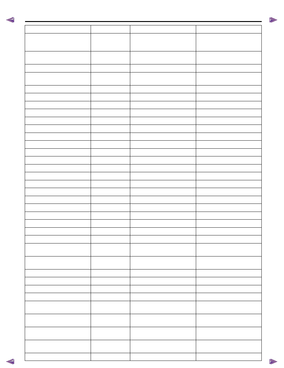
Scan Tool Parameter
Units Displayed
Typical Data Value at Engine Idle
Typical Data Value at 2000RPM
ENGINE CONTROL SYSTEM (4JK1/4JJ1) 6E-49
Cam/ Crank Sensor Signal
Synchronization Status
Asynchronous/ No
Crank Signal/
Synchronous
Synchronous
Synchronous
Engine Runtime
Time (hour:
minute: second)
Varies
Varies
Vehicle Speed
km/h / MPH
0 km/h / 0 MPH
0 km/h / 0 MPH
Transmission Gear
Out of gear/ 1st/
2nd/ 3rd/ 4th/ 5th
Out of gear
Out of gear
Starter Switch
On/Off
On
On
Ignition Switch
On/Off
On
On
Ignition Voltage
Volts
11.0 to 15.0 volts
11.0 to 15.0 volts
Battery Voltage
Volts
11.0 to 15.0 volts
11.0 to 15.0 volts
Fuel Pump Relay Command
On/ Off
On
On
Swirl Control Solenoid Command
On/ Off
On
On
Fuel Filter Switch
On/ Off
On
On
A/C Request Signal
On/ Off
Off
Off
A/C Relay Command
On/ Off
Off
Off
Park/ Neutral Switch
Neutral/ In Gear
Neutral
Neutral
Glow Relay Command
On/ Off
Off
Off
Glow Plug Lamp Command
On/ Off
Off
Off
Brake Switch 1
Applied/ Released
Released
Released
Brake Switch 2
Applied/ Released
Released
Released
Clutch Pedal Switch
Applied/ Released
Released
Released
Cruise Main Lamp Command
On/ Off
Off
Off
Cruise Main Switch
On/ Off
Off
Off
Cruise Cancel Switch
On/ Off
On
On
Cruise Resume Switch
On/ Off
Off
Off
Cruise Set Switch
On/ Off
Off
Off
MIL Command (Malfunction
Indicator Lamp)
On/ Off
Off
Off
SVS Lamp Command (Service
Vehicle Soon)
On/ Off
Off
Off
Limp Home Mode
None/ 1/ 2/ 3/ 4
None
None
Distance While MIL is Activated
km/ Mile
0 km/ 0 Mile
0 km/ 0 Mile
Engine Runtime With MIL Active
minutes
0
0
Total Engine Overspeed Event
Counter
Varies
Varies
Total Engine Coolant
Overtemperature Event
Counter
Varies
Varies
Total Fuel Temperature
Overtemperatrure Event
Counter
Varies
Varies
Total Intake Air Temperature
Overtemperaure Event
Counter
Varies
Varies
Immobilizer Function
Programmed
Yes/ No
Yes
Yes
Wrong Immobilizer Signal
Yes/ No
No
No
Scan Tool Parameter
Units Displayed
Typical Data Value at Engine Idle
Typical Data Value at 2000RPM

6E-50 ENGINE CONTROL SYSTEM (4JK1/4JJ1)
Scan Tool Data Definitions
This information will assist in emission or driveability
problems. The displays can be viewed while the vehicle
is being driven. Always perform the Diagnostic System
Check - Engine Controls first. The Diagnostic System
Check will confirm proper system operation.
Engine Speed
This parameter displays the rotational speed of the
crankshaft as calculated by the ECM based on inputs
from the crankshaft position (CKP) sensor or camshaft
position (CMP) sensor.
Desired Idle Speed
This parameter displays the idle speed requested by
the ECM. The ECM will change desired idle speed
based on engine coolant temperature and other inputs.
Calculate Engine Load
This parameter displays the engine load in percent
based on inputs to the ECM from various engine
sensors. The scan tool will display a lower percentage
when the engine is at idle with little or no load. The
scan tool will display a higher percentage when the
engine is running at high engine speed under a heavy
load.
Coolant Temperature
This parameter displays the temperature of the engine
coolant as calculated by the ECM using the signal from
the engine coolant temperature (ECT) sensor. The
scan tool will display a low temperature when the ECT
sensor signal voltage is high, and a high temperature
when the ECT sensor signal voltage is low.
Engine Coolant Temperature Sensor
This parameter displays the voltage signal sent to the
ECM from the engine coolant temperature (ECT)
sensor. ECT sensor is a range of value indicating a low
voltage when the temperature is high, and a high
voltage when the temperature is low.
Intake Air Temperature
This parameter displays the temperature of the intake
air as calculated by the ECM using the signal from the
intake air temperature (IAT) sensor. The scan tool will
display a low temperature when the IAT sensor signal
voltage is high, and a high temperature when the IAT
sensor signal voltage is low.
Intake Air Temperature Sensor
This parameter displays the voltage signal sent to the
ECM from the intake air temperature (IAT) sensor. IAT
sensor is a range of value indicating a low voltage
when the temperature is high, and a high voltage when
the temperature is low.
Fuel Temperature
This parameter displays the temperature of the fuel as
calculated by the ECM using the signal from the fuel
temperature (FT) sensor. The scan tool will display a
low temperature when the FT sensor signal voltage is
high, and a high temperature when the FT sensor
signal voltage is low.
Fuel Temperature Sensor
This parameter displays the voltage signal sent to the
ECM from the fuel temperature (FT) sensor. FT sensor
is a range of value indicating a low voltage when the
temperature is high, and a high voltage when the
temperature is low.
MAF (Mass Air Flow)
This parameter displays the air flow into the engine as
calculated by the ECM based on the mass air flow
(MAF) sensor input. The scan tool will display a high
value at higher engine speeds, and a low value at lower
engine speed.
MAF Sensor (Mass Air Flow)
This parameter displays the voltage signal sent to the
ECM from the mass air flow (MAF) sensor. MAF sensor
is a range of value indicating a low voltage at lower
engine speed, and a high voltage at a higher engine
speeds.
Barometric Pressure
This parameter displays the barometric pressure
(BARO) as calculated by the ECM using the signal from
the BARO sensor. The scan tool will display a low
barometric pressure in high altitude area.
Barometric Pressure Sensor
This parameter displays the voltage signal sent to the
ECM from the barometric pressure (BARO) sensor.
BARO sensor is a range of value indicating a low
voltage in high altitude area, and a middle voltage in
sea level.
Immobilizer Signal
Yes/ No
Yes
Yes
Security Wait Time
Inactive/ Time
(hour: minute:
second)
Inactive
Inactive
Scan Tool Parameter
Units Displayed
Typical Data Value at Engine Idle
Typical Data Value at 2000RPM
Нет комментариевНе стесняйтесь поделиться с нами вашим ценным мнением.
Текст