Isuzu KB P190. Manual — part 133
4C1-28 FRONT WHEEL DRIVE
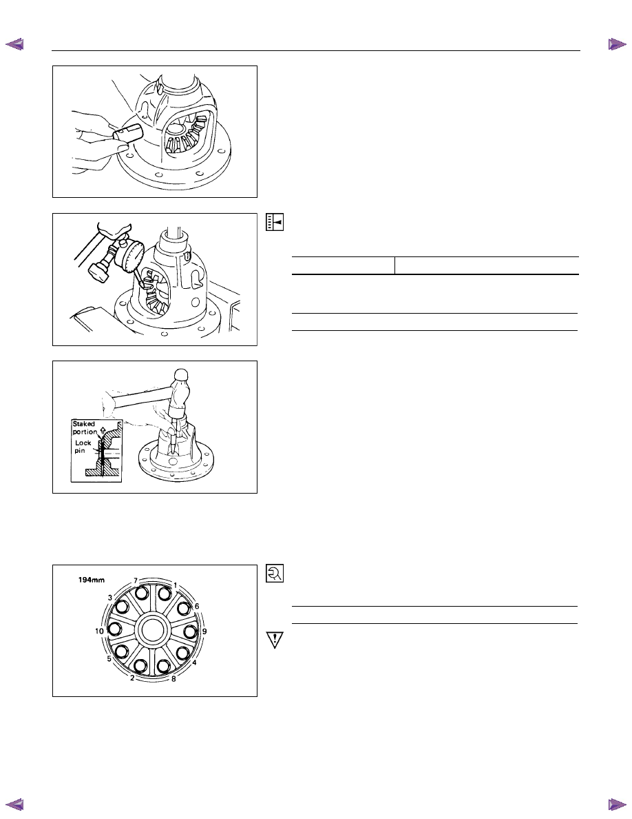
5. Cross Pin
(1) Be sure to install the cross pin so that it is in alignment with
the lock pin hole in the differential cage.
(2) Adjust the backlash between the side gear and the pinion
gear.
mm(in)
Backlash
0.10 - 0.20 (0.004 - 0.008)
Thickness of thrust washers available
mm(in)
1.00, 1.05, 1.10 (0.039, 0.041, 0.043)
6. Lock Pin
After lock pin installation, stake the cage to prevent discharge
of the lock pin.
7. Ring Gear
When installing the ring gear, apply LOCTITE 271 or
equivalent to the threaded hole and bolt.
8. Bolt
Tighten the bolts in diagonal sequence as illustrated.
Bolt Torque
N
⋅m (kgf⋅m/lb⋅ft)
108 (11.0/80)
Note :
Discard used bolts and install new ones.
Note that all bolts have a left hand thread.
FRONT WHEEL DRIVE 4C1-29
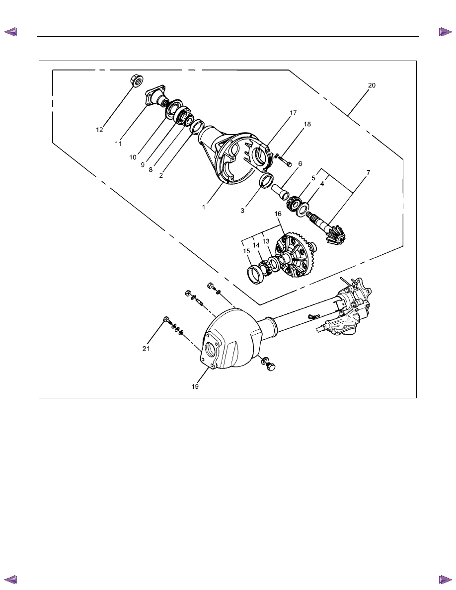
Major Components
RTW54CLF000201
Reassembly Steps
1.
Diff.
carrier
▲ 2. Outer bearing outer race
▲ 3. Inner bearing outer race
▲ 4. Adjust shim
▲ 5. Inner bearing
▲ 6. Collapsible spacer
7.
Pinion
gear
8.
Outer
bearing
▲ 9. Oil seal
10.
Dust
cover
11.
Flange
▲12. Flange nut
▲13. Adjust shim
▲14. Side bearing
15. Bearing outer race
16. Diff. cage assembly
▲17. Bearing cap
▲18. Bolt
19.
Axle
case
▲20. Differential assembly
21.
Bolt
4C1-30 FRONT WHEEL DRIVE
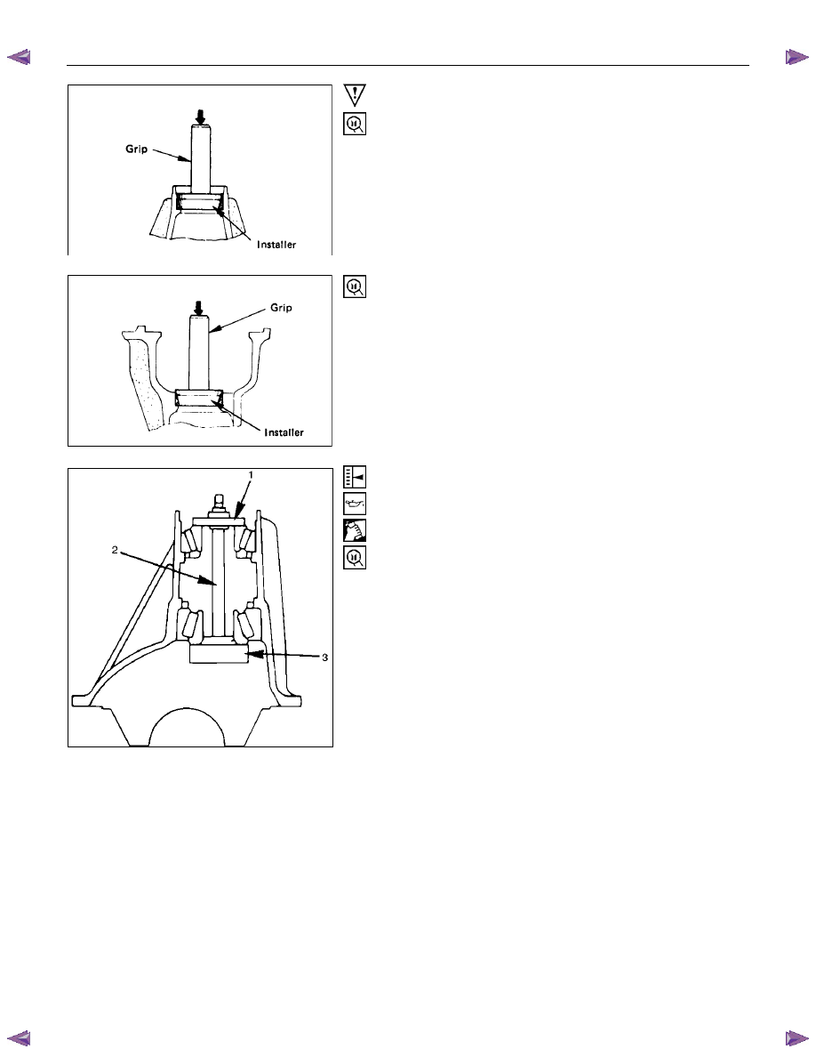
Important Operations
2. Outer Bearing Outer Race
Installer : 9-8522-1141-0
Grip :
5-8840-0007-0
3. Inner Bearing Outer Race
Installer : 9-8522-1274-0
Grip :
5-8840-0007-0
4. Adjust Shim
Adjustment of drive pinion mounting distance
(1) Apply gear oil to the inner and outer drive pinion bearing.
Clean the pinion setting gage set.
Then install the gage set together with the inner and outer
bearings.
1. Pilot
: 5-8840-2085-0
2. Nut and bolt : 5-8840-2089-0
3. Gage plate : 5-8840-2087-0
FRONT WHEEL DRIVE 4C1-31
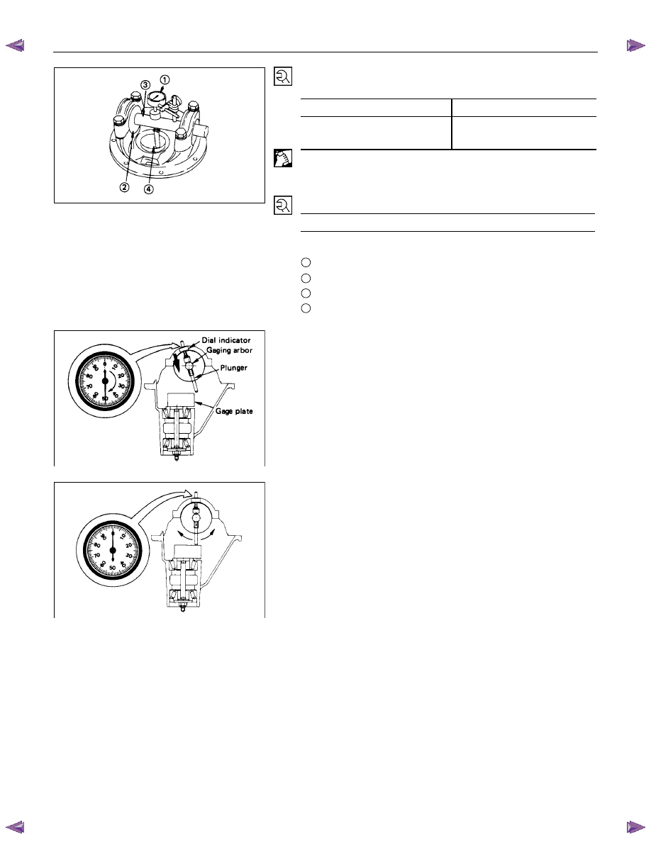
Tighten the nut to the specified torque.
N
⋅m (kgf⋅m/lb⋅in)
New bearing
2.3 (0.23/20)
Used bearing
0.98 - 1.18
(0.10 – 0.12/9 – 10)
(2) Clean the side bearing bores. Install the dial indicator with
the discs and Arbor. Install and tighten the bearing caps to
the specified torque.
Torque N
⋅m (kgf⋅m/lb⋅ft)
98 (10.0/72)
1
Dial indicator : 5-8840-0126-0
2
Disc (2 pcs.) : 5-8840-2088-0
3
Arbor
: 5-8840-0128-0
4
Gage plate : 5-8840-2087-0
(3) Set the dial indicator to “0”. Place it on the mounting post of
the gaging arbor with the contact button touching the
indicator pad. Force the dial indicator downward until the
needle has made a half turn clockwise. Tighten down the
dial indicator in this position.
(4) Position the plunger on the gage plate. Move the gaging
arbor slowly back and forth and locate the position at which
the dial indicator shows the greatest deflection. At this
point, once again set the dial indicator to “0”.
Repeat the procedure to verify the “0” setting.
Нет комментариевНе стесняйтесь поделиться с нами вашим ценным мнением.
Текст