Isuzu KB P190. Manual — part 1213
7D-22 TRANSFER CASE
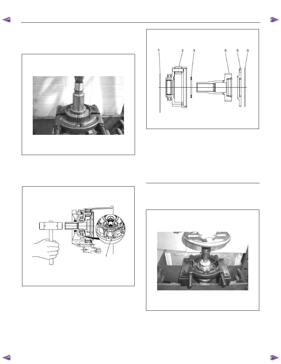
15. Remove the snap ring from the main shaft.
16. Use a press to remove the 2-4 hub from the main
shaft.
17. Spread the edges of the retaining ring (1) while lightly
tapping on the sun gear input shaft end. Remove the
carrier and gear assembly from the transfer case.
226R300020
18. Remove the dog teeth snap ring from the carrier and
gear assembly.
19. Remove the planetary dog teeth and the sun gear
input shaft together with the thrust needle bearing.
2260R300021
20. Remove the carrier snap ring.
21. Use a press to remove the ball bearings.
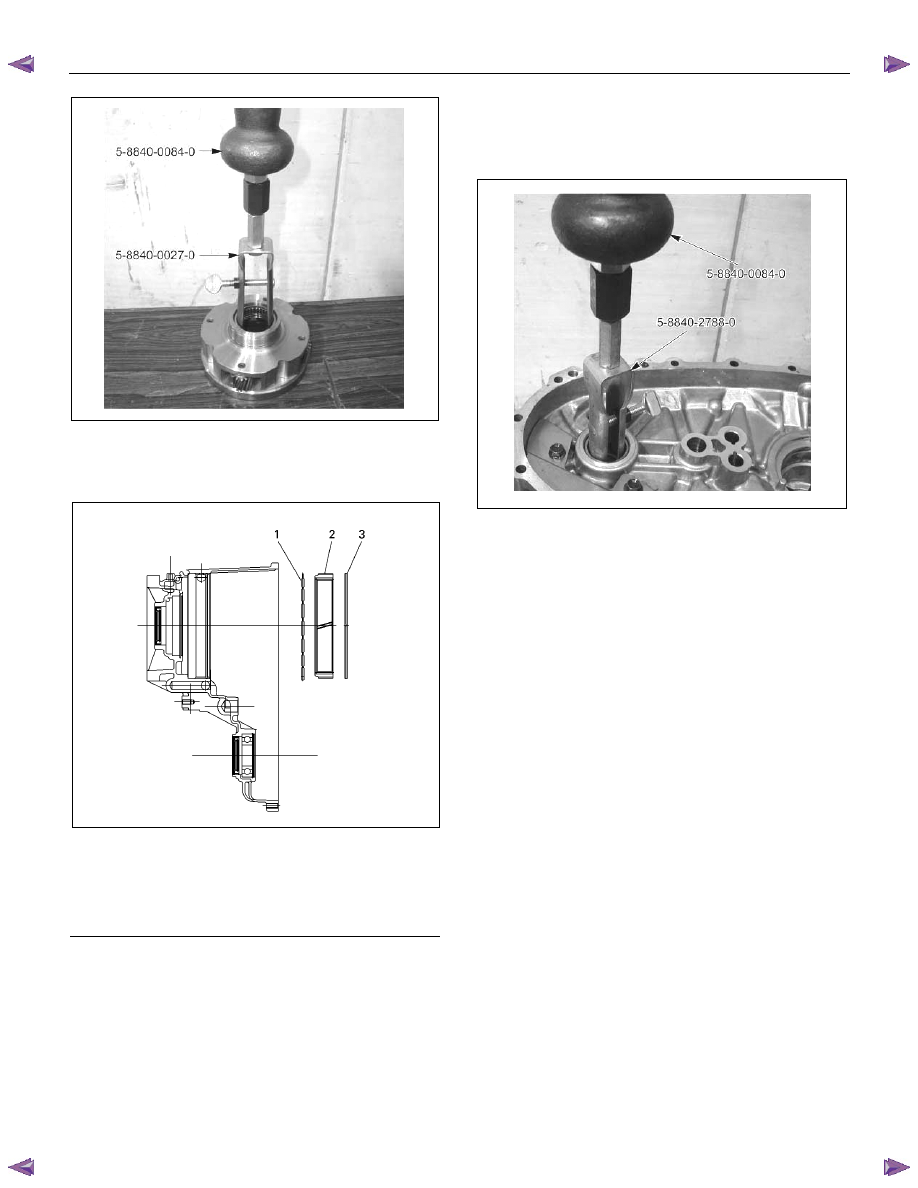
22. Use a sliding hammer (5-8840-0084-0) and a needle
bearing replacer (5-8840-0027-0) to remove the
needle bearing from the center of the carrier and gear
assembly.
Legend
(1) Outer Retaining Ring
(2) Carrier and Gear ASM
(3) Thrust needle Bearing
(4) Sungear Input Shaft
(5) Planetary DogTeeth
(6) Dog Teeth Snap Ring
TRANSFER CASE 7D-23
23. Remove the retaining ring (spiral type) together with
the internal gear and the damper ring.
226R300004
24. Remove the snap ring.
25. Use a press to remove the front output shaft ball
bearings.
26. Remove the oil pump wire snap ring from the rear
cover.
27. Use a sliding hammer (5-8840-0084-0) and a needle
bearing replacer (5-8840-2788-0) to remove the
needle bearing from the front output shaft.
P1010023
Legend
(1) Dumper Ring
(2) Internal Gear
(3) Retaining Ring
7D-24 TRANSFER CASE
Internal Component Disassembly and Reassembly
226R300017
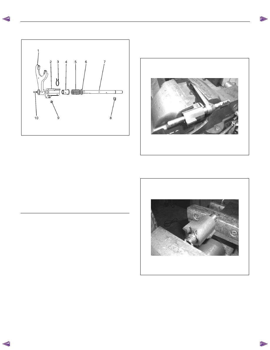
H-L Shift Disassembly
1. Remove the guide roller.
2. Use a vise to compress the H-L shift spring (inside the
assembly)
3. Remove the outer snap ring.
4. Remove the shift block assembly from the shift rod.
5. Use a socket and a vise to compress the shift block
spring (inside the assembly)
6. Remove the inner retaining ring.
7. Remove the collar (rear)
8. Remove the shift block spring.
9. Remove the collar (front)
10. Remove the shift block assembly
11. Remove the spring pin.
12. Remove the shift arm.
Legend
(1) Shift Arm
(2) Shift Block Assembly
(3) Inner Retaining Ring
(4) Collar (Front)
(5) Shift Block Spring
(6) Collar (Rear)
(7) Shift Rod
(8) Outer Snap Ring
(9) Guide Roller
(10) Spring Pin
TRANSFER CASE 7D-25
H-L shift reassembly
1. Install the shift arm to the shift rod.
2. Install the spring pin. The top of the pin must be flush
with the surrounding surface (no projection).
3. Install the front collar, the spring, and the rear collar to
the shift block in that order.
4. Use a socket and a vise to compress the shift block
spring.
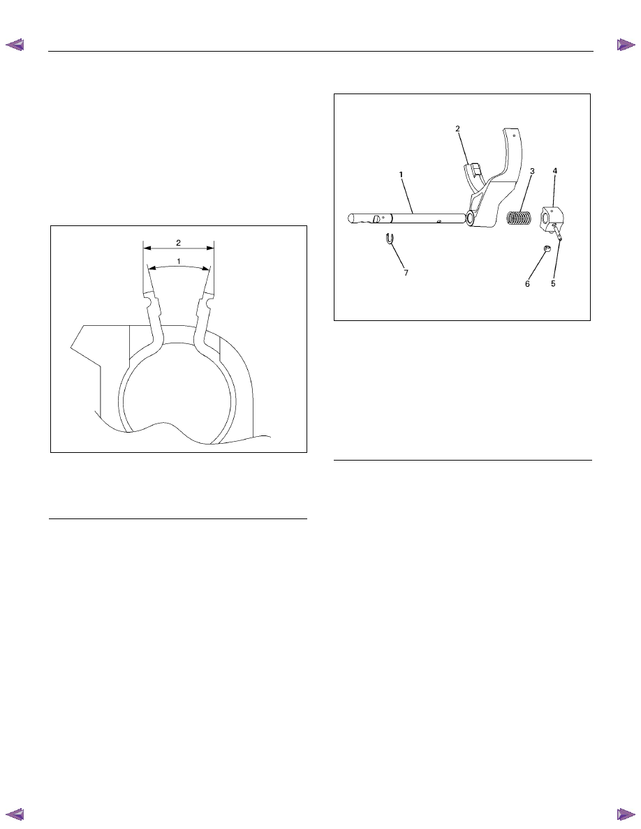
5. Install the inner retaining ring. Be sure that the arm
aperture width is within the specified limit.
226R300014
6. Install the shift lock assembly to the shift rod.
7. Use a socket and a vise to compress the H-L shift
spring.
8. Install the outer snap ring.
9. Install the guide roller.
2-4 shift ASM
226R300016
2-4 shift disassembly
1. Remove the guide roller.
2. Compress the spring and remove the snap ring.
3. Remove the shift arm.
4. Remove the spring.
5. Remove the spring pin.
6. Remove the shift block assembly.
7. Remove the shift rod.
Legend
(1) 25.62
°
(2) 14.1mm
Legend
(1) Shift Rod
(2) Shift Arm
(3) Spring
(4) Shift Block Assembly
(5) Spring Pin
(6) Guide Roller
(7) Snap Ring
Нет комментариевНе стесняйтесь поделиться с нами вашим ценным мнением.
Текст