Isuzu KB P190. Manual — part 1214
7D-26 TRANSFER CASE
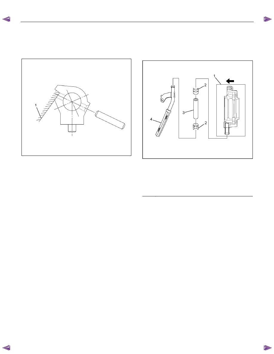
2-4 shift reassembly
1. Install the shift block assembly to the shift rod.
2. Install the spring pin. The head of the pin must not
project beyond the surface (1) of the shift block.
226R300015
3. Install the spring.
4. Install the shift arm.
5. Compress the spring and install the snap ring.
6. Install the guide roller.
Oil pump disassembly
1. Remove the clamps securing the screen.
2. Remove the screen.
3. Remove the clamps securing the hose.
4. Remove the hose.
NOTE: To maintain and protect oil pump function, the
pump is constructed so that it cannot be disassembled.
Under no conditions attempt to disassemble the pump.
Oil pump reassembly
1. Tighten the clamps to secure the hose.
2. Tighten the clamps to secure the screen.
NOTE: Be careful in the direction of clamps.
RTW37DSH000101
Legend
(1) Oil Pump Assembly
(2) Clamp
(3) Hose
(4) Screen Assembly
TRANSFER CASE 7D-27
Inspection and Repair
1. Make the necessary repair or parts replacement if
wear, damage or any other abnormal conditions are
found during inspection.
2. Wash all parts thoroughly in clean solvent. Be sure all
old lubricant, metallic particles, dirt, or foreign material
are removed from the surfaces of every part. Apply
compressed air to each oil feed port and channel in
each case half to remove any obstructions or cleaning
solvent residue.
Inspection and Repair (Transfer Case
Assembly)
When wear, damage, or any other defects are observed
during the inspection, the part or parts must be repaired
or replaced. Wash all the parts with clean detergent, and
check that old oil, metallic particles, dirt, or foreign
materials are completely removed. Blow the air into oil
holes and grooves to remove foreign materials or
residual detergent.
Chain
• Check whether the face that contacts the sprocket is
free from excessive wear or damage. If defects are
observed, replace the part.
• If the chain interference mark is found on the inside
wall of the transfer cover or the chain is so slack that a
skipped engagement occurs between the chain and
sprocket, replace the chain.
Sprocket
• Check whether the sprocket tooth surface is
excessively worn or damaged, and there is evidence
of burrs, chipping, wear, or damage on the gear
spline. Remove minor flaws or scratches with oil
stone. If excessive wear or damage is observed,
replace the part.
• If excessive wear or damage is observed on the
sprocket inside sliding surface, replace the part.
Gear
• Check whether the gear tooth surface is excessively
worn or damaged, and there is evidence of burrs,
chipping, wear, or damage on the gear spline.
• Remove minor flaws or scratches with oil stone. If
excessive wear or damage is observed, replace the
part.
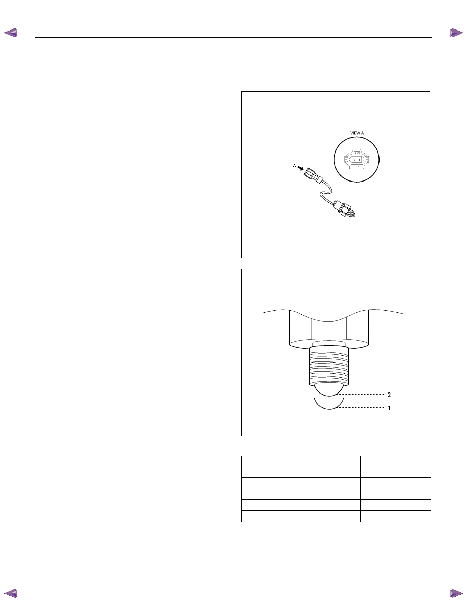
2-4 and Neutral Switch
• Check the continuity of 2-4 and Neutral switch.
If defects are observed, replace the 4H and 4L switch.
221R300001
261R300003
Switch
Stroke
2-4 Switch
Signal
Neutral Switch
Signal
Terminal
1 to 2
Terminal
1 to2
1 Open Close
2 Close Open
7D-28 TRANSFER CASE
Oil Pump
• Remove foreign materials from the strainer. If the
strainer is damaged, replace it.
If the area into which the shaft is inserted is excessively
worn or damaged, replace the oil pump assembly.
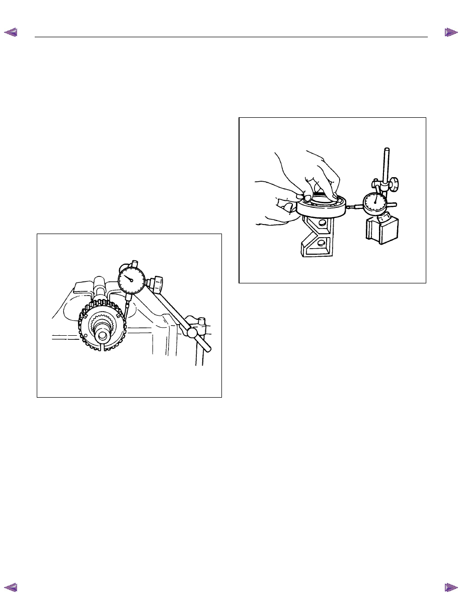
Clutch Hub Spline Play
• Set a dial indicator to the clutch hub to be measured.
• Move the clutch hub as far as possible to both the
right and the left.
Note the dial indicator reading.
• If the measured value exceeds the specified limit, the
clutch hub must be replaced.
Clutch hub spline play
Standard: 0-0.1 mm (0-0.004 in)
Limit: 0.2 mm (0.008 in)
226RS042
Bearings
1. Inspect the condition of all the needles and ball
bearings. Wash bearings thoroughly in a cleaning
solvent. Apply compressed air to the bearings.
NOTE: Do not allow the bearings to spin. Turn them
slowly by hand. Spinning bearings may damage the
rollers.
2. Lubricate the bearings with a light oil and check them
for roughness by slowly turning the race by hand.
Ball Bearing Play
1. Use a dial indicator to measure the ball bearing play.
2. If the measured value exceeds the specified limit, the
ball bearing must be replaced.
Limit: 0.2 mm (0.008 in)
226R3043
Synchronizers
The synchronizer hubs and sliding sleeves are a selected
assembly and should be kept together as originally
assembled.
Clean synchronizer components with clean solvent and
air dry.
Inspect the components for the following:
• Teeth for wear, scuffs, nicks, burrs or breaks.
• Keys and springs for wear, cracks or distortion,
replace if these conditions are present.
• If scuffed, nicked or burred conditions cannot be
corrected with a soft stone or crocus cloth, replace the
component.
TRANSFER CASE 7D-29
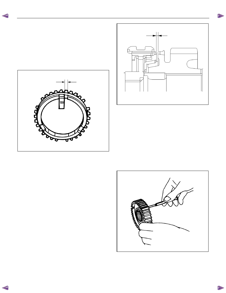
Block Ring and Insert Clearance
1. Use a vernier caliper to measure the clearance
between the block ring and the insert.
2. If the measured value exceeds the specified limit, the
block ring and the insert must be replaced.
Block ring and insert clearance
Standard: 2.46-2.74 mm (0.097-0.108 in)
Limit: 3.0 mm (0.118 in)
226RS037
2WD-4WD Synchronizer (3-Cone)
1. Use a thickness gauge to measure the clearance
between the block ring and the dog teeth.
2. If the measured value exceeds the specified limit, the
2WD-4WD synchronizer assembly must be replaced.
Block ring and dog teeth clearance
Standard: 1.5 mm (0.059 in)
Limit: 0.8 mm (0.031 in)
226R300019
Clutch Hub and Insert Clearance
1. Clutch Hub and Insert Clearance
2. Use a thickness gauge to measure the clearance
between the clutch hub and the insert.
3. If the measured value exceeds the specified limit, the
clutch hub and the insert must be replaced.
Clutch hub and insert clearance
Standard: 0.01-0.19 mm (0.0004-0.0075 in)
Limit: 0.3 mm (0.012 in)
226RS038
Detent Springs
1. Inspect the springs for distortion, cracks or wear.
Replace if these conditions are present.
Нет комментариевНе стесняйтесь поделиться с нами вашим ценным мнением.
Текст