Isuzu KB P190. Manual — part 1131
UNIT REPAIR (JR405E) 7A4-47
Free length – 36.4 mm (1.433 in)
Linear diameter – 1.2 mm (0.047 in)
21C&L-SUB31
Reassembly steps
Coat the parts with ATF before installing them.
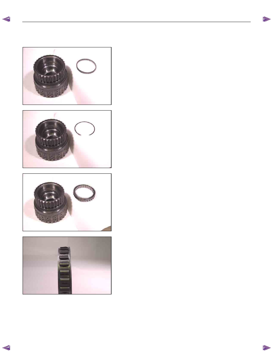
1. Bearing
Install the bearing into the low clutch drum.
22C&L-SUB30
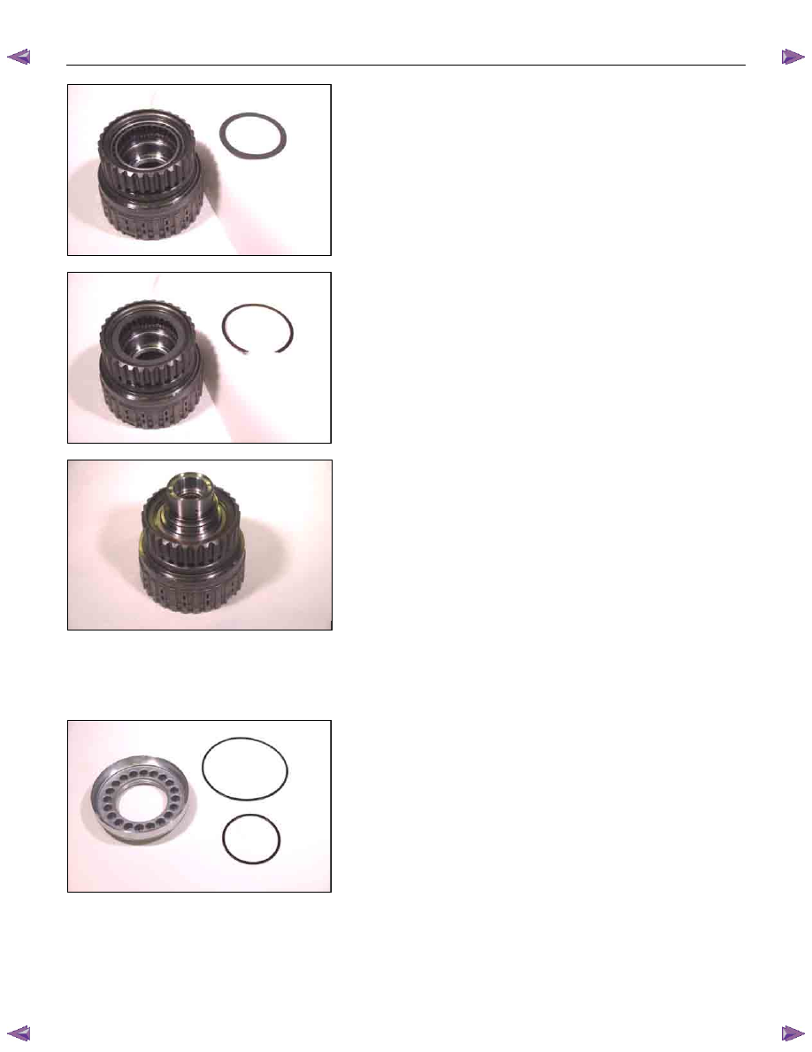
2. Snap ring
Install the snap ring to the low clutch drum.
23C&L-SUB28
3. Low one-way clutch
Install the low one-way clutch to the low clutch drum.
24C&L-SUB33
NOTE:
The flanged side of the low one-way clutch must face the
outside.
7A4-48 UNIT REPAIR (JR405E)
25C&L-SUB27
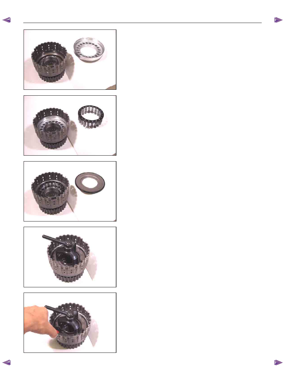
4. Side plate
Install the side plate.
26C&L-SUB26
5. Snap ring
Install the snap ring to the low clutch drum.
27C&L-SUB58
• Attach the low one-way clutch inner race to the low
clutch drum in the opposite direction of the normal
position.
• Rotate the one-way clutch inner race clockwise. It
should turn smoothly with little resistance.
• Rotate the low one-way clutch inner race
counterclockwise.
It should immediately lock (rotation is impossible).
If it does not, check the low one-way clutch installation
direction.
Inspect and replace the low one-way clutch if required.
• Remove the low one-way clutch inner race.
• Reverse the low clutch drum.
28C&L-SUB32
6. Low clutch piston
• Install new seal rings to the low clutch piston.
UNIT REPAIR (JR405E) 7A4-49
29C&L-SUB22
• Install the low clutch piston to the low clutch drum.
30C&L-SUB21
7. Return spring
Install the return spring to the low clutch piston.
31C&L-SUB20
8. Cancel cover
• Carefully center the cancel cover and install it.
NOTE:
If the cancel cover is not centered, the cover outside seal
ring gum will be forced into the low clutch piston area
where it will be damaged.
32C&L-SUB18
• Install the spring compressor to the low clutch.
Spring compressor: 5-8840-2759-0
33C&L-SUB19
9. Snap ring
• Use the spring compressor to carefully force the cancel
cover down.
NOTE:
To avoid damage to the return spring, use only as much
force as is required to press the cancel cover into place.
• Install new snap ring to the low clutch drum.
7A4-50 UNIT REPAIR (JR405E)
34C&L-SUB15
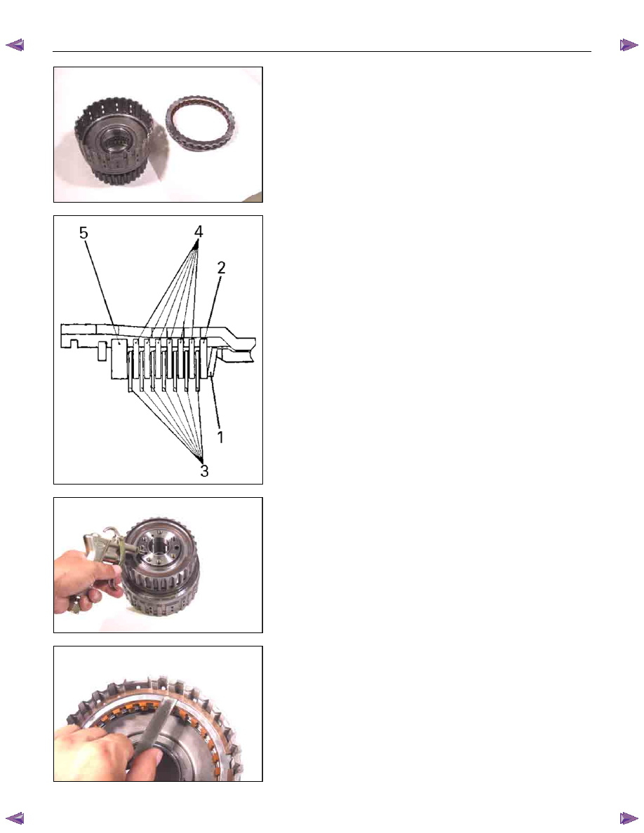
10.Dish plate, drive plates, driven plates, and retaining
plate
Install the low clutch dish plate (1), the 2 mm thick driven
plate (2), the 7 drive plates (3), the other 6 driven plates (4),
and the retaining plate (5).
NOTE:
The dish plate side with the identification mark must face
the driven plate.
248L300006
11.Snap ring
Install the snap ring to the low clutch drum.
NOTE:
Ensure the attachment direction of dish plate is correct.
35C&L-SUB38
36CLEAR06
Inspection
• Insert the low one-way clutch inner race to the low clutch
drum.
• Force compressed air (390 kPa/4.0 kgf/cm
2
/57 psi)
through the oil passages of the low one-way clutch inner
race to check low clutch operation.
If the low clutch does not operate, the seal rings may be
damaged or the parts may have been installed in the
wrong order.
• Measure the clearance between the low clutch retaining
plate and the snap ring.
If the clearance is outside the specified range, replace
the existing plate with a new plate of the proper size
(thickness).
Low clutch retaining plate and snap ring clearance:
0.9~1.3 mm (0.035~0.051 in)
Available low clutch retaining plate thicknesses
3.8 mm (0.150 in)
4.0 mm (0.157 in)
Нет комментариевНе стесняйтесь поделиться с нами вашим ценным мнением.
Текст