Isuzu KB P190. Manual — part 596
6E–214
ENGINE DRIVEABILITY AND EMISSIONS
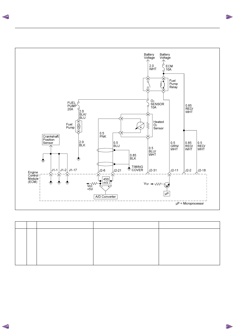
DIAGNOSTIC TROUBLE CODE (DTC) P1171 FUEL SUPPLY SYSTEM LEAN
DURING POWER ENRICHMENT
Condition for setting the DTC and action taken when the DTC sets
Circuit Description
The engine control module (ECM) internal circuitry can
identify if the vehicle fuel system is capable of supplying
adequate amounts of fuel during heavy acceleration
(power enrichment). The ECM monitors the voltage of
the oxygen sensor during power enrichment. When a
power enrichment mode of operation is requested
during “Closed Loop” operation (by heavy acceleration),
the ECM will provide more fuel to the engine. Under
these conditions the ECM should detect a “rich”
condition (high oxygen sensor voltage). If this “rich”
exhaust is not detected at this time, a Diagnostic
Trouble Code P1171 will set. A plugged fuel filter or
restricted fuel line can prevent adequate amounts of fuel
from being supplied during power enrichment mode.
Code
Type
DTC Name
DTC Setting Condition
Fail-Safe (Back Up)
P1171
D
Fuel Supply System Lean During
Power Enrichment
1. No DTC relating to MAP sensor, TPS,
EVAP purge, ECT sensor, CKP sensor,
VSS, injector control circuit and ignition
control circuit.
2. Engine coolant temperature is more than
60 deg. C.
3. Mass air flow is below 13.5m/s.
4. O
2
sensor bank 1 output voltage is below
350mV in power enrichment mode.
No fail-safe function.

ENGINE DRIVEABILITY AND EMISSIONS
6E–215
Diagnostic Aids
Check for the following conditions:
• Heated oxygen sensor wiring - The sensor pigtail
may be routed incorrectly and contacting the exhaust
system.
• Poor ECM to engine block ground.
• Fuel pressure - The system will go lean if pressure is
too low. The ECM can compensate for some
decrease. However, if fuel pressure is too low, a
diagnostic Trouble Code P1171 may be set. Refer to
Fuel System Diagnosis.
• Lean injector(s) - Perform “Injector Balance Test.”
• Vacuum leaks - Check for disconnected or damaged
vacuum hoses and for vacuum leaks at the intake
manifold, throttle body, and PCV system.
• Exhaust leaks - An exhaust leak may cause outside
air to be pulled into the exhaust gas stream past the
HO2S, causing the system to appear lean. Check for
exhaust leaks that may cause a false lean condition
to be indicated.
• Fuel contamination - Water, even in small amounts,
can be delivered to the fuel injectors. The water can
cause a lean exhaust to be indicated, Excessive
alcohol in the fuel can also cause this condition.
Refer to Fuel System Diagnosis for the procedure to
check for fuel contamination.
Diagnostic Trouble Code (DTC) P1171
Fuel Supply System Lean During Power Enrichment
Step
Action
Value(s)
Yes
No
1
Was the “On-Board Diagnostic (OBD) System Check”
performed?
—
Go to Step 2
Go to On Board
Diagnostic
(OBD) System
Check
2
1. Connect the Tech 2.
2. Review and record the failure information.
3. Select “F0: Read DTC Infor By Priority” in “F0:
Diagnostic Trouble Code”.
Is the DTC P1171 stored as “Present Failure”?
—
Go to Step 3
Refer to
Diagnostic Aids
and Go to Step
3
3
1. Using the Tech2, ignition “On” and engine “Off”.
2. Select “Clear DTC Information” with the Tech2 and
clear the DTC information.
3. Operate the vehicle and monitor the “F5: Failed
This Ignition” in “F2: DTC Information”.
Was the DTC P1171 stored in this ignition cycle?
—
Go to Step 4
Refer to
Diagnostic Aids
and Go to Step
4
4
1. Using the Tech 2, ignition “On” and engine “Off”.
2. Monitor the “Throttle Position” in the data display.
Does the Tech 2 indicate correct “Throttle Position” in
accordance with accelerator pedal operation?
—
Go to Step 6
Go to Step 5
5
Check for the following conditions.
• Objects blocking the throttle valve.
• Incorrectly installed.
If a problem is found, repair as necessary.
Was the problem found?
—
Verify repair
Go to Step 12
6
1. Using the Tech 2, ignition “On” and engine “On”.
2. Monitor the “Manifold Absolute Pressure” in the
data display.
Does the Tech 2 indicate correct “Manifold Absolute
Pressure” in accordance with engine speed or
acceleration?
—
Go to Step 8
Go to Step 7

6E–216
ENGINE DRIVEABILITY AND EMISSIONS
7
Remove the MAP sensor and check for the following
conditions.
• Objects blocking the air cleaner.
• Objects blocking the MAP sensor.
• Objects blocking the throttle valve.
• Vacuum leaking at intake duct.
• Vacuum leaking at throttle body.
If a problem is found, repair as necessary.
Was the problem found?
—
Verify repair
Go to Step 13
8
1. Using the Tech 2, ignition “On” and engine “On”.
2. Select the “Miscellaneous Test” and perform the
“IAC Control” in the “IAC System”.
3. Operate the Tech 2 in accordance with procedure.
Was the engine speed changed, when the IAC valve
is operating step by step?
—
Go to Step 10
Go to Step 9
9
Check for the following conditions.
• Objects blocking the IAC valve.
• Objects blocking the throttle valve.
• Vacuum leaking at throttle body.
If a problem is found, repair as necessary.
Was the problem found?
—
Verify repair
Go to Step 14
10
Check for injector for the affected bank.
Refer to “Injector Coil Test & Injector Balance Test
Procedure” 6E-98 page.
Was the injector operation correct?
—
Go to Step 11
Refer to Injector
Coil Test &
Injector
Balance Test
Procedure
11
Check for fuel pressure.
Refer to “Fuel System Diagnosis” 6E-108 page.
Was the fuel pressure correct?
—
Go to Step 15
Refer to Fuel
System
Diagnosis
12
Replace the TPS.
Is the action complete?
—
Verify repair
—
13
Replace the MAP sensor.
Is the action complete?
—
Verify repair
—
14
Replace the IAC valve.
Is the action complete?
—
Verify repair
—
15
Replace the O
2
sensor.
Was the problem solved?
—
Verify repair
Go to Step 16
16
Is the ECM programmed with the latest software
release?
If not, download the latest software to the ECM using
the “SPS (Service Programming System)”.
Was the problem solved?
—
Verify repair
Go to Step 17
17
Replace the ECM.
Is the action complete?
IMPORTANT: The replacement ECM must be
programmed. Refer to section of the Service
Programming System (SPS) in this manual.
Following ECM programming, the immobilizer system
(if equipped) must be linked to the ECM. Refer to
section 11 “Immobilizer System-ECM replacement” for
the ECM/Immobilizer linking procedure.
—
Verify repair
—
Step
Action
Value(s)
Yes
No

ENGINE DRIVEABILITY AND EMISSIONS
6E–217
DIAGNOSTIC TROUBLE CODE (DTC) P1625 ECM SYSTEM RESET
Condition for setting the DTC and action taken when the DTC sets
Circuit Description
The engine control module (ECM) monitors unexpected
ECM reset. This will not turn on MIL light on, only
records code DTC P1625.
Diagnostic Aids
Check for the follwing conditions:
• P1625 alone stored does not need diagnosis. Clear
DTC code.
NOTE: DTC P1625 is a DTC to record a ECM reset
history. If DTC P1625 is not reset and no engine
abnormality occurs after learing the DTC, no farther
diagnostic procedures are required.
Diagnostic Trouble Code (DTC) P1625 ECM System Reset
Code
Type
DTC Name
DTC Setting Condition
Fail-Safe (Back Up)
P1625
B
ECM System Reset
ECM reset has occurred other than “On”.
Engine control disabled.
Step
Action
Value(s)
Yes
No
1
Was the “On-Board Diagnostic (OBD) System Check”
performed?
—
Go to Step 2
Go to On Board
Diagnostic
(OBD) System
Check
2
1. Connect the Tech 2.
2. Review and record the failure information.
3. Select “F0: Read DTC Infor By Priority” in “F0:
Diagnostic Trouble Code”.
Is the DTC P1625 stored as “Present Failure”?
—
Go to Step 3
Refer to
Diagnostic Aids
and Go to Step
3
3
1. Using the Tech2, ignition “On” and engine “Off”.
2. Select “Clear DTC Information” with the Tech2 and
clear the DTC information.
3. Operate the vehicle and monitor the “F5: Failed
This Ignition” in “F2: DTC Information”.
Was the DTC P1625 stored in this ignition cycle?
—
Go to Step 4
Refer to
Diagnostic Aids
and Go to Step
4
4
Is the Immobilizer function programmed in the ECM?
—
Verify repair
Go to Step 5
5
Is the ECM programmed with the latest software
release?
If not, download the latest software to the ECM using
the “SPS (Service Programming System)”.
Was the problem solved?
—
Verify repair
Go to Step 6
6
Replace the ECM.
Is the action complete?
IMPORTANT: The replacement ECM must be
programmed. Refer to section of the Service
Programming System (SPS) in this manual.
Following ECM programming, the immobilizer system
(if equipped) must be linked to the ECM. Refer to
section 11 “Immobilizer System-ECM replacement” for
the ECM/Immobilizer linking procedure.
—
Verify repair
—
Нет комментариевНе стесняйтесь поделиться с нами вашим ценным мнением.
Текст