Isuzu KB P190. Manual — part 597
6E–218
ENGINE DRIVEABILITY AND EMISSIONS
DIAGNOSTIC TROUBLE CODE (DTC) P1626 IMMOBILIZER NO SIGNAL
Condition for setting the DTC and action taken when the DTC sets
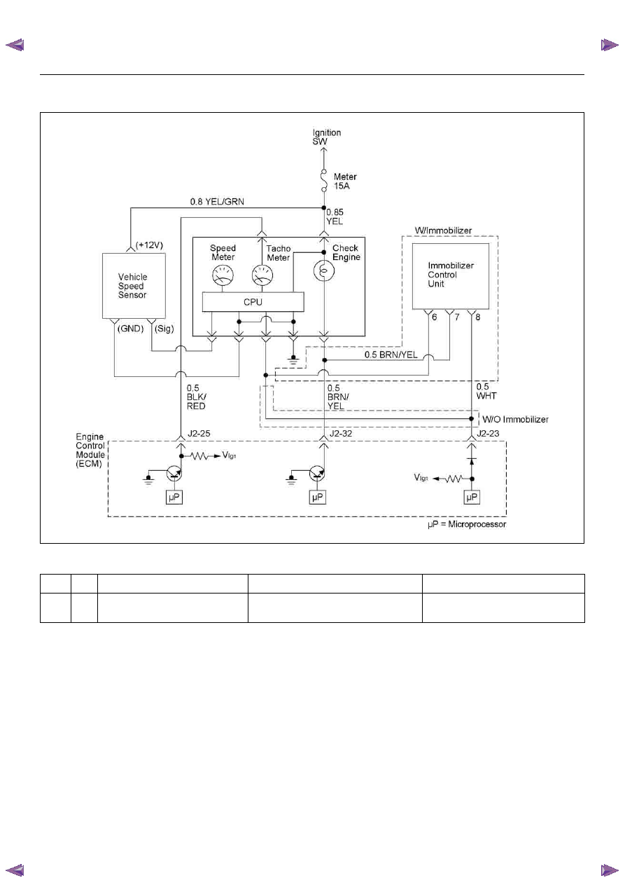
Circuit Description
The ECM decides whether that is an abnomality in the
immobilizer control system. DTC P1626 is recorded by
the ECM when no response from immobiliser.
Diagnostic Aids
Check for the following conditions:
• Poor connection at ECM and Immobilizer-Inspect
harness connectors for backed out terminals,
improper mating, broken locks, improperly formed or
damaged terminals, and poor terminal to wire
connection.
• Damaged harness Inspect the wiring harness for
damage, If the harness appears to be OK, disconnect
the ECM and Immobilizer, turn the ignition “ON” and
observe a voltmeter connected to the suspect driver
circuit at the ECM and Immobilizer harnass connector
while moving connectors and wiring harnesses
relates to the MIL. A change in voltage will indicate
the location of the fault.
Code
Type
DTC Name
DTC Setting Condition
Fail-Safe (Back Up)
P1626
-
Immobilizer No Signal
No response from immobilizer control unit.
1. Engine does not start.
2. Check engine lamp flash.
ENGINE DRIVEABILITY AND EMISSIONS
6E–219
Diagnostic Trouble Code (DTC) P1626 Immobilizer No Signal
Step
Action
Value(s)
Yes
No
1
Was the “On-Board Diagnostic (OBD) System Check”
performed?
—
Go to Step 2
Go to On Board
Diagnostic
(OBD) System
Check
2
1. Connect the Tech 2.
2. Review and record the failure information.
3. Select “F0: Read DTC Infor By Priority” in “F0:
Diagnostic Trouble Code”.
Is the DTC P1626 stored as “Present Failure”?
—
Go to Step 3
Refer to
Diagnostic Aids
and Go to Step
3
3
1. Using the Tech2, ignition “On” and engine “Off”.
2. Select “Clear DTC Information” with the Tech2 and
clear the DTC information.
3. Operate the vehicle and monitor the “F5: Failed
This Ignition” in “F2: DTC Information”.
Was the DTC P1626 stored in this ignition cycle?
—
Go to Step 4
Refer to
Diagnostic Aids
and Go to Step
4
4
1. Using the Tech 2, ignition “On” and engine “Off”.
2. Select “Immobilizer” in the system selection menu
“Body”.
3. Select “Read DTC Info Ordered By Priority” in the
“Diagnositic Trouble Code”.
Was the DTC B0007 stored in this ignition cycle?
—
Refer to
“Immobilizer
Workshop
Manual” & Go
to DTC Chart
B0007
Go to Step 5
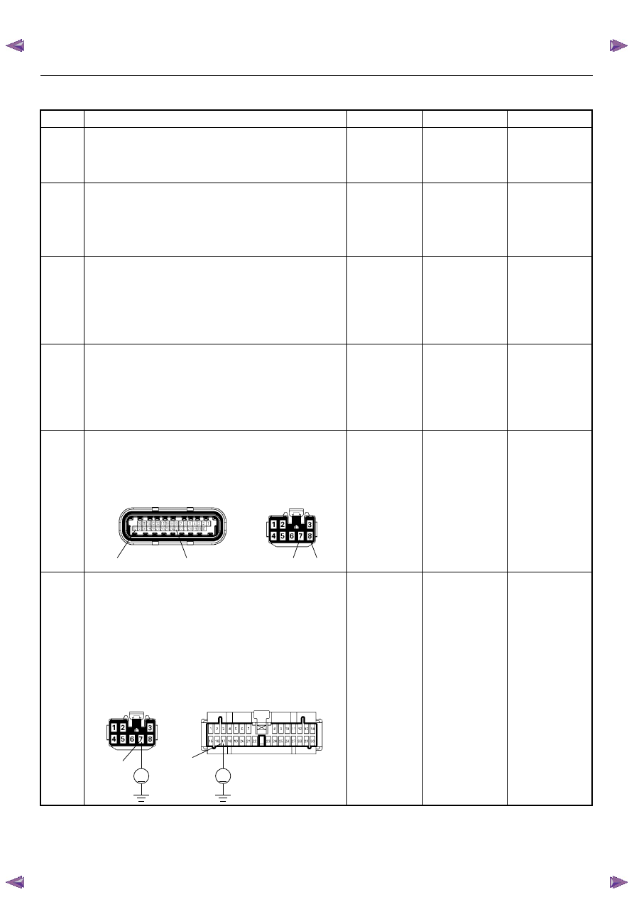
5
Check for poor/faulty connection at the immobilizer
control unit connector or ECM connector. If a poor/
faulty connection is found, repair as necessary.
Was the problem found?
—
Verify repair
Go to Step 6
6
Using the DVM and check the “CHECK ENGINE”
lamp circuit.
1. Ignition “Off”, engine “Off”.
2. Disconnect the meter connector and immobilizer
control unit connector.
3. Ignition “On”.
4. Check the circuit for short to power supply circuit.
Was the problem found?
—
Repair faulty
harness and
verify repair
Go to Step 7
32
23
7
8
C-56(J2)
B-68
V
V
B-24
B-68
17
7
6E–220
ENGINE DRIVEABILITY AND EMISSIONS
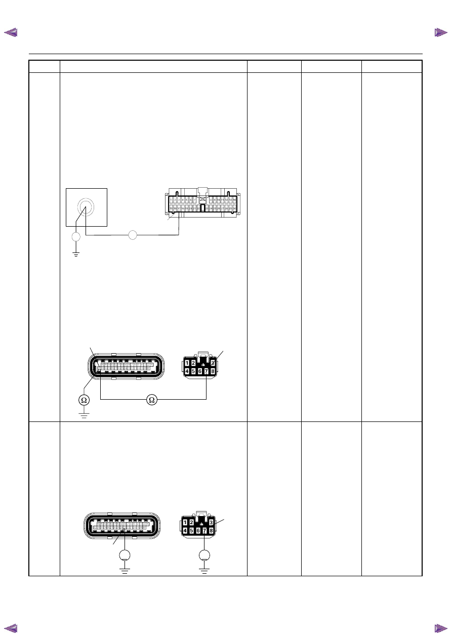
7
Using the DVM and check the “CHECK ENGINE”
lamp circuit.
Breaker box is available:
1. Ignition “Off”, engine “Off”.
2. Install the breaker box as type A. (ECM
disconnected) Refer to 6E-88 page.
3. Disconnect the immobilizer control unit connector.
4. Check the circuit for open or short to ground
circuit.
Was the problem found?
Breaker box is not available:
1. Ignition “Off”, engine “Off”.
2. Disconnect the the immobilizer control unit
connector and ECM connector.
3. Check the circuit for open or short to ground
circuit.
Was the problem found?
—
Repair faulty
harness and
verify repair
Go to Step 8
8
Using the DVM and check the VSS signal circuit.
1. Ignition “Off”, engine “Off”.
2. Disconnect the immobilizer control unit connector
and ECM connector.
3. Ignition “On”.
4. Check the circuit for short to power supply circuit.
Was the problem found?
—
Repair faulty
harness and
verify repair
Go to Step 9
Step
Action
Value(s)
Yes
No
J2-32
Breaker Box
B-24
17
Ω
Ω
C-56(J2)
32
7
B-68
V
V
C-56(J2)
23
7
B-68
ENGINE DRIVEABILITY AND EMISSIONS
6E–221
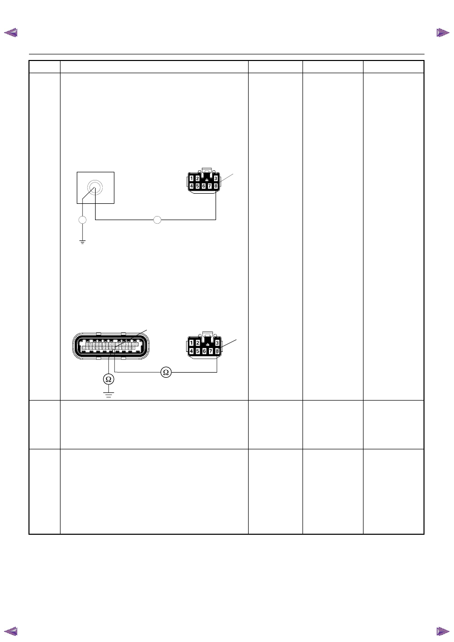
9
Using the DVM and check the VSS signal circuit.
Breaker box is available:
1. Ignition “Off”, engine “Off”.
2. Install the breaker box as type A. (ECM
disconnected) Refer to 6E-88 page.
3. Disconnect the immobilizer control unit connector.
4. Check the circuit for open or shot to ground circuit.
Was the problem found?
Breaker box is not available:
1. Ignition “Off”, engine “Off”.
2. Disconnect the immobilizer control unit connector
and ECM connector.
3. Check the circuit for open or short to ground
circuit.
Was the problem found?
—
Repair faulty
harness and
verify repair
Go to Srtep 10
10
Is the ECM programmed with the latest software
release?
If not, download the latest software to the ECM using
the “SPS (Service Programming System)”.
Was the problem solved?
—
Verify repair
Go to Step 11
11
Replace the ECM.
Is the action complete?
IMPORTANT: The replacement ECM must be
programmed. Refer to section of the Service
Programming System (SPS) in this manual.
Following ECM programming, the immobilizer system
(if equipped) must be linked to the ECM. Refer to
section 11 “Immobilizer System-ECM replacement” for
the ECM/Immobilizer linking procedure.
—
Verify repair
—
Step
Action
Value(s)
Yes
No
J2-23
Breaker Box
B-68
8
Ω
Ω
23
B-68
C-56(J2)
8
Нет комментариевНе стесняйтесь поделиться с нами вашим ценным мнением.
Текст