Isuzu KB P190. Manual — part 1221
7D1-10 TRANSFER CONTROL SYSTEM
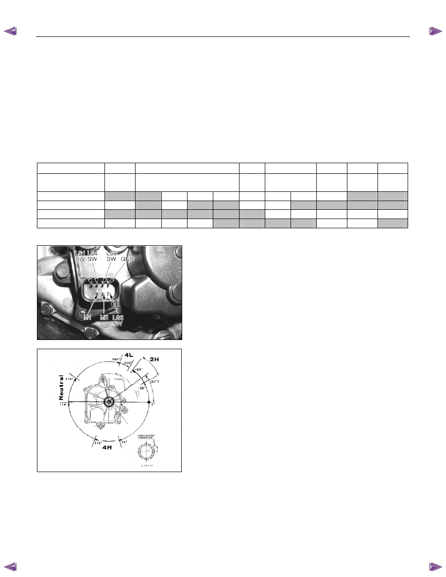
Transfer Actuator
Method of confirming the actuator position detection
(limit) switch
The actuator indicates the continuity condition of combinations,
as shown in the list below between the 4 detection (limit) switch
pins and the GND pin along the direction of the notch of the
output shaft spline. Check that these combinations are as
specified.
The middle condition between these positions (4 patterns in
the case of 2H-4H) is either of the combinations shown below,
depending upon manufacturing variations of the switch plate.
2H
2H-4H
4H
4H-N
N
N-L
4L
Direction of output
shaft notch (outline)
-54
° to
-29
°
-29
° to 74°
74
° to
110
°
110
° to 179°
179
° to
215
°
215
° to
285
°
285
° to
300
°
LS1
Close
Close
Open
Open
Open
Open
Open
Open
Open
Close
Close
LS2 Open
Close
Open
Close
Close
Open
Open
Close
Close
Close
Close
LS3
Close
Close
Close
Close
Close
Close
Open
Open
Open Open Open
LS4 Open
Open
Open
Open
Close
Close
Close
Close
Open Open Close
Continuity between each pin and GND pin. (Continuity also exists between CLOSE pins.)
Transfer Actuator Connector
7B4-PDF6
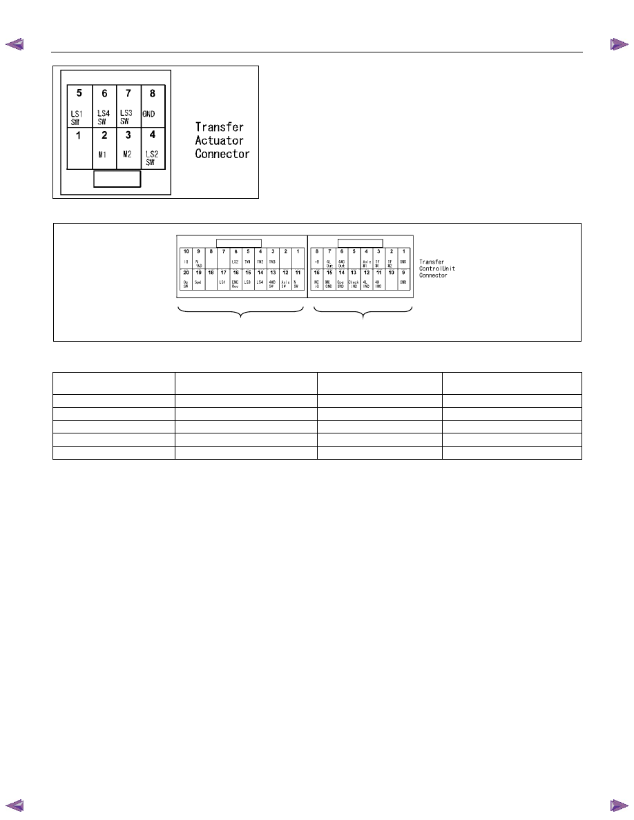
TRANSFER CONTROL SYSTEM 7D1-11
Method of checking the position detection switch harness
Disconnect the vehicle harness connector on the transfer
controller side, and the vehicle harness connector on the
transfer actuator side as shown in the wiring diagram. Check
the continuity between the following connector pins, ensure
there is no continuity between those pins and GND or power
source.
Check that there is continuity between the GND pin and the
vehicle GND on the transfer actuator, and there is no continuity
between the GND pin and another power source.
C-112 C-111
Vehicle harness connector pin No. (connector of mating parts of the harness is shown in this figure)
Name of pin
T/F controller side
T/F actuator side
Remarks
LS1 C-112,
17
5
LS2 C-112,
6
4
LS3 C-112,
15
7
LS4 C-112,
14
6
GND
C-111, 1, 9
8
7D1-12 TRANSFER CONTROL SYSTEM
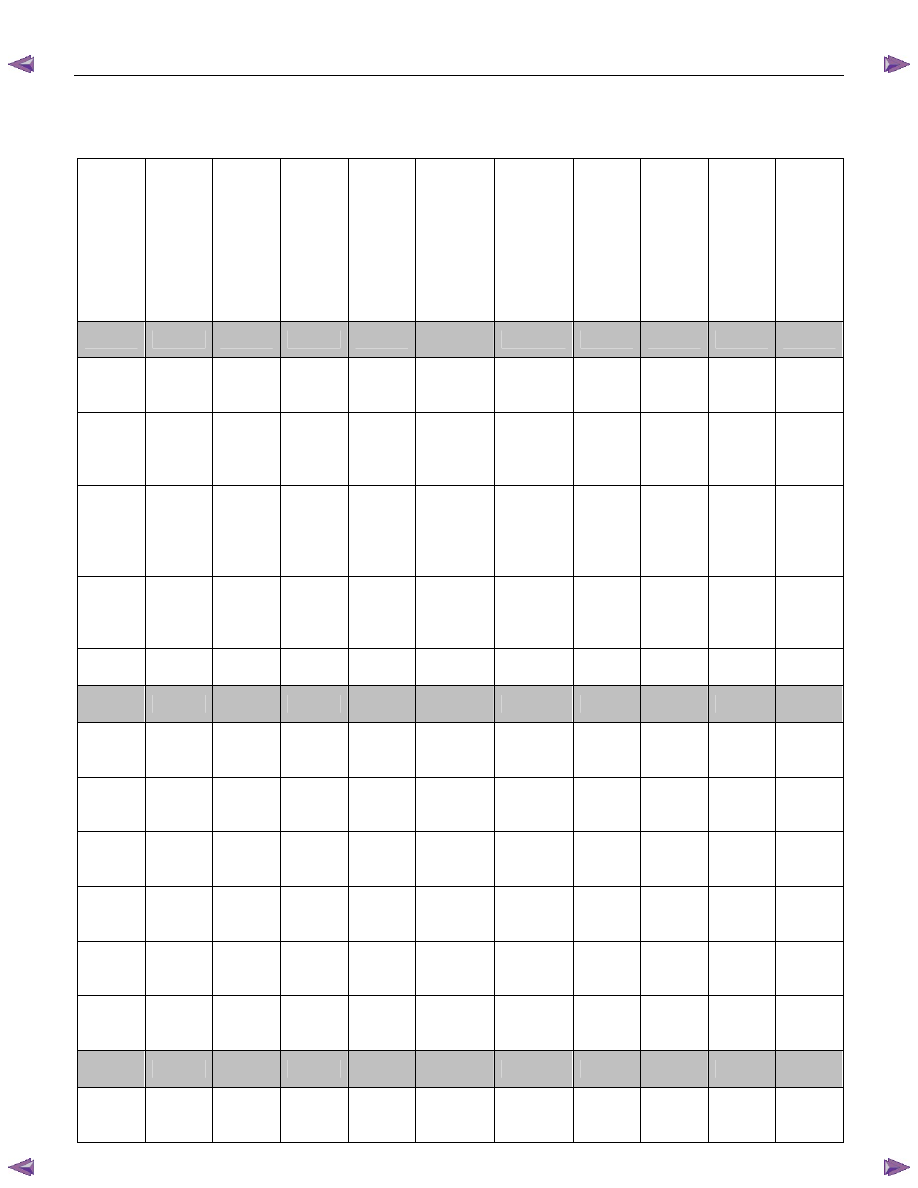
Functions of Switch and indicator Lamp
Transfer-related indicator lamp and switch function
Item
4WD
lamp
4L lamp
Neutral
lamp
Check
4WD
warning
light
4WD
switch
Actuator
detection
(limit)
switches
LS1, LS2,
LS3. and
LS4
1 = on
2 = off
Transfer
4WD
switch
Transfer
neutral
switch
SOF
actuator
switch
Or
Axle
dummy
Remarks
2H
Off
Off
Off
Off
No
operation
1,0,1,0
Open
Open
Open
-----
4H start
of
operation
Off Off Off Off
4H position
for 0.1
second
1,0,1,0 Open Open Open
Switch
operation
sensor
Start of
operation
Blinking
(2HZ)
Off Off Off
No
operation
1,1,1,0
0,0,1,0
0,1,1,0
0,1,1,1
Open Open Open
2H to 4H
while
driving
During
operation
(Synchro)
Blinking
(2HZ)
Off Off Off
No
operation
1,1,1,0
0,0,1,0
0,1,1,0
0,1,1,1
Open Open Open
2H to 4H
using
synchro
and
retrial
During
operation
(Axle
drive)
Blinking
(2HZ)
Off Off Off
No
operation
0,0,1,1 Closed Open Open
Axle
drive
Axle
waiting
Blinking
(2HZ)
Off Off Off
No
operation
0,0,1,1 Closed Open Open
Axle
drive
4H
On
Off
Off
Off
No
operation
0,0,1,1
Closed
Open
Closed
-----
4L start
of
operation
On Off Off Off
4L position
for 0.1
second
0,0,1,1 Closed Open Closed
Switch
operation
sensor
Start of
operation
On
Blinking
(2HZ)
Off Off
No
operation
0,0,0,1
0,1,0,1
Closed Open Closed
4H to 4L
while
driving
During
operation
(N)
Off
Blinking
(2HZ)
Off Off
No
operation
0,0,0,1
0,1,0,1
Closed Closed Closed
4H to 4L
through
neutral
During
operation
(N)
Off
Blinking
(2HZ)
Off Off
No
operation
0,1,0,0 Closed Closed Closed
4H to 4L
through
neutral
During
operation
(N)
Off
Blinking
(2HZ)
Off Off
No
operation
1,1,0,0 Closed Closed Closed
4H to 4L
through
neutral
4L
waiting
On
Blinking
(2HZ)
Off Off
No
operation
1,1,0,1 Closed Closed Closed
4H to 4L
while
waiting
4L
On
On
Off
Off
No
operation
1,1,0,1
Closed
Open
Closed
-----
4H start
of
operation
On Off Off Off
4H position
for 0.1
second
1,1,0,1 Closed Open Closed
Switch
operation
sensor
TRANSFER CONTROL SYSTEM 7D1-13
Item
4WD
lamp
4L lamp
Neutral
lamp
Check
4WD
warning
light
4WD
switch
Actuator
detection
(limit)
switches
LS1, LS2,
LS3. and
LS4
1 = on
2 = off
Transfer
4WD
switch
Transfer
neutral
switch
SOF
actuator
switch
Or
Axle
dummy
Remarks
During
operation
On
Blinking
(2HZ)
Off Off
No
operation
1,1,0,1 Closed Open Closed
4L to 4H
while
driving
During
operation
(N)
Off
Blinking
(2HZ)
Off Off
No
operation
1,1,0,0 Closed Closed Closed
4L to 4H
through
neutral
During
operation
Off
Blinking
(2HZ)
Off Off
No
operation
0,1,0,1
0,0,0,1
Closed Closed Closed
4L to 4H
while
driving
4H
waiting
Off
Blinking
(2HZ)
Off
Off
No
operation
0,0,1,1
Closed
Closed
Closed
4L to 4H
while
waiting
4H
On
Off
Off
Off
No
operation
0,0,1,1
Closed
Open
Closed
-----
2H start
of
operation
On Off Off Off
2H position
for 0.1
second
0,0,1,1 Closed Open Closed
Switch
operation
sensor
Start of
operation
Blinking
(2HZ)
Off Off Off
No
operation
0,1,1,1
0,1,1,0
0,0,1,0
1,1,1,0
Closed Open Closed
2H to 4H
while
driving
During
operation
(Axle)
Blinking
(2HZ)
Off Off Off
No
operation
0,1,1,1
0,1,1,0
0,0,1,0
1,1,1,0
Open Open Closed
Axle
drive
Axle
waiting
Blinking
(2HZ)
Off
Off
Off
No
operation
1,0,1,0
Open
Open
Closed
Axle
waiting
2H
Off
Off
Off
Off
No
operation
1,0,1,0
Open
Open
Open
-----
Нет комментариевНе стесняйтесь поделиться с нами вашим ценным мнением.
Текст