Isuzu KB P190. Manual — part 1220

7D1-6 TRANSFER CONTROL SYSTEM
the 4
×2 - 4×4 shift rod. When moving in 4×2 direction, a spring
standby mechanism is provided between the rod and sleeve so
that the rod is positioned at the 4
×2 position, while the sleeve is
at the 4
×4 position.
This mechanism is provided to protect the shift mechanism
from the force and to prevent movement of the sleeve
(torsional torque etc. of the drive system). By releasing the
preventive force, the sleeve can move to the 4
×2 state by the
spring force.
Neutral switch
The neutral switch detects the movement of the shift rod
driving the high-low sleeve.
PUSH close is achieved with the PUSH close switch when the
shift rod is positioned between the High and the Low, at the
neutral state.
High-Low Sleeve & Arm
The spring standby mechanism is provided for the high-low
sleeve in both directions of the high-low shift rod. Therefore,
the rod position and the actual sleeve position may be offset in
some cases.
This system is provided to protect the shift mechanism from a
collision due to coincidence of the high and low phases of the
engaged splines. By giving rotational force to the preventing
phase coincidence, the splines are moved to the proper
engagement position by the spring force.
Shift actuator
The output shaft is rotated by the built-in motor and the transfer
position is switched.
Detection (limit) switches to detect the rotating angle of the
output shaft that is provided to the actuator at 4 positions.
These are connected to the transfer controller through the
vehicle harness to constantly transmit the actuator operating
angle and changes in its transfer status.
7B4-PDF2
4WD indicator (in meter panel)
This lamp indicates the following items:
Valve check
Drive condition (2WD-4WD)
Operating condition (2Hz: Actuator in operation, mechanism
standby)
Restrictions on operation (4Hz, including indication of
interrupted operation due
to excessive load)
TRANSFER CONTROL SYSTEM 7D1-7
7B4-PDF3
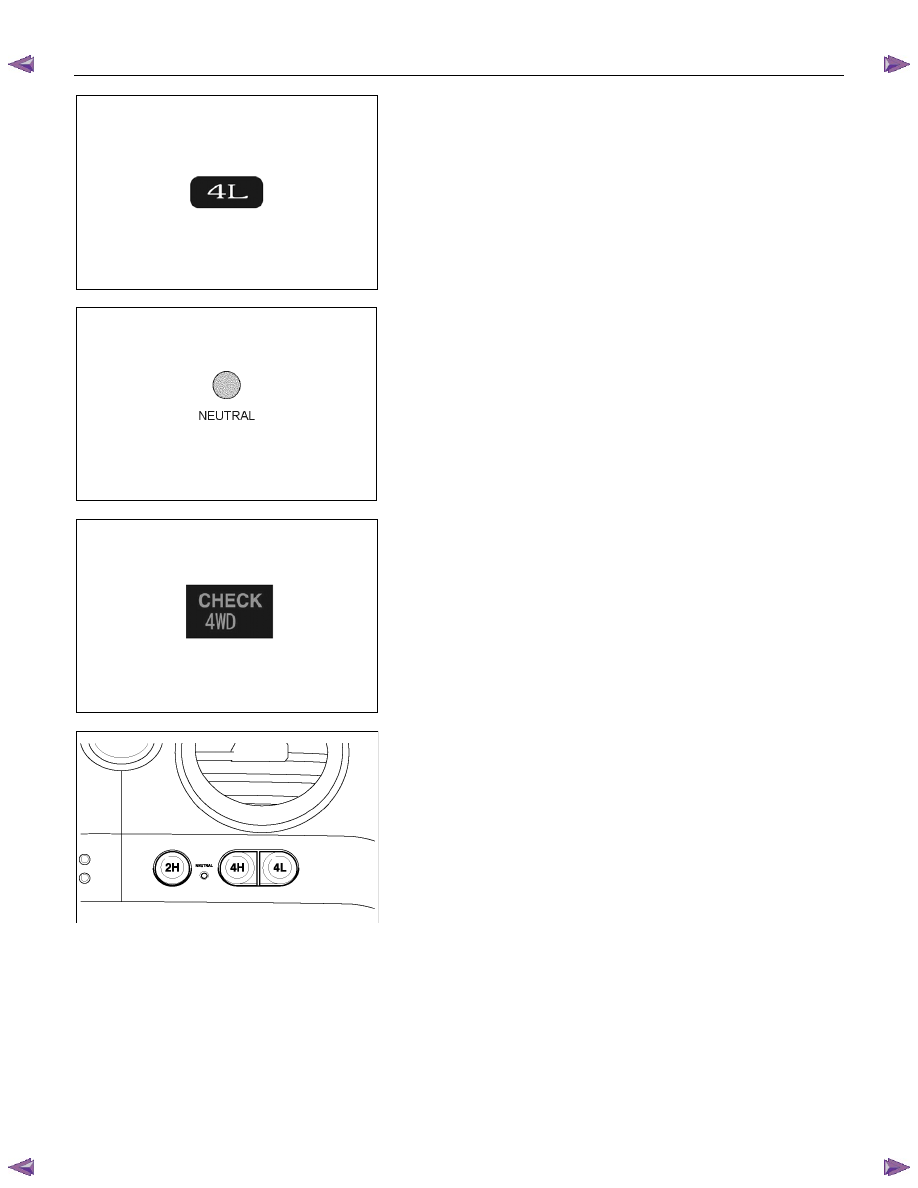
4L indicator (in meter panel)
This lamp indicates following items:
Valve check
Driving status (High-Low)
Operating status (2Hz: Actuator in operation, mechanism
standby)
Restrictions on operation (4Hz)
RTW77DSH000601
Neutral indicator (in operation switch panel)
This LED indicates following items:
LED check
Driving status (Neutral)
Operating status (2Hz: Actuator in operation, mechanism
standby)
Restrictions on operation (4Hz)
7B4-PDF5
Check 4WD warning light (in meter panel)
This light indicates following items:
Valve check
Faulty actuator limit SW, and circuit related faults with the limit
switch
RTW77DSH000501
4WD switch
Switch to transmit a switching command to the 2H, 4H,
Neutral, or 4L position.
It comprises 3 PUSH momentary switches. By pushing the 2H
and 4L switches for 10 seconds,
operation is changed to the neutral position.
To shift from the neutral to another position, push another
switch for 10 seconds.
7D1-8 TRANSFER CONTROL SYSTEM
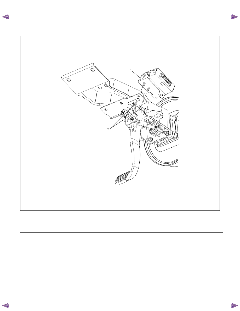
Transfer controller
RHD
RTW77DMF000101
Legend
(1) Transfer Controller
(2) Nut
TRANSFER CONTROL SYSTEM 7D1-9
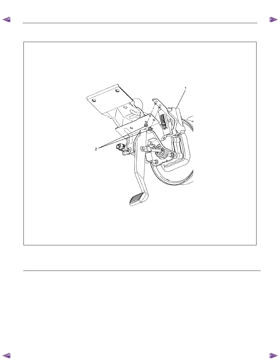
LHD
RUW77DMF000101
Legend
(1) Transfer Control Unit
(2) Nut
Нет комментариевНе стесняйтесь поделиться с нами вашим ценным мнением.
Текст