Isuzu KB P190. Manual — part 656
Engine Mechanical – V6
Page 6A1–145
8
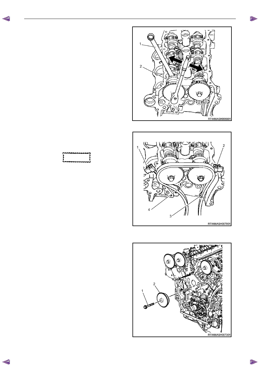
Loosen the camshaft sprocket bolt.
N O T E
• Use an open-end wrench (1) at the camshaft
hex (2) to prevent camshaft/engine rotation.
• Do not remove the camshaft sprocket bolt at
this time.
• If the camshaft timing chain has already
been removed proceed to step 12.
Figure 6A1 – 232
9
Install Tool No. EN-46108 (1 and 2) to retain the
timing chain (3 and 4).
10
Firmly tighten the wing nuts of Tool No. EN-46108.
CAUTION
Ensure the tips of Tool No. EN-46108 are
fully engaged into the timing chain and the
wing nuts are tight and the timing chain is
taught.
11
Mark the timing chain and the respective location on
both camshaft sprocket.
N O T E
Ensure the camshaft timing chain and the
camshaft sprocket are marked for correct
reassembly.
Figure 6A1 – 233
12
Remove the bolt (1) attaching the left-hand exhaust
camshaft sprocket (2) and remove the sprocket.
Figure 6A1 – 234
Engine Mechanical – V6
Page 6A1–146
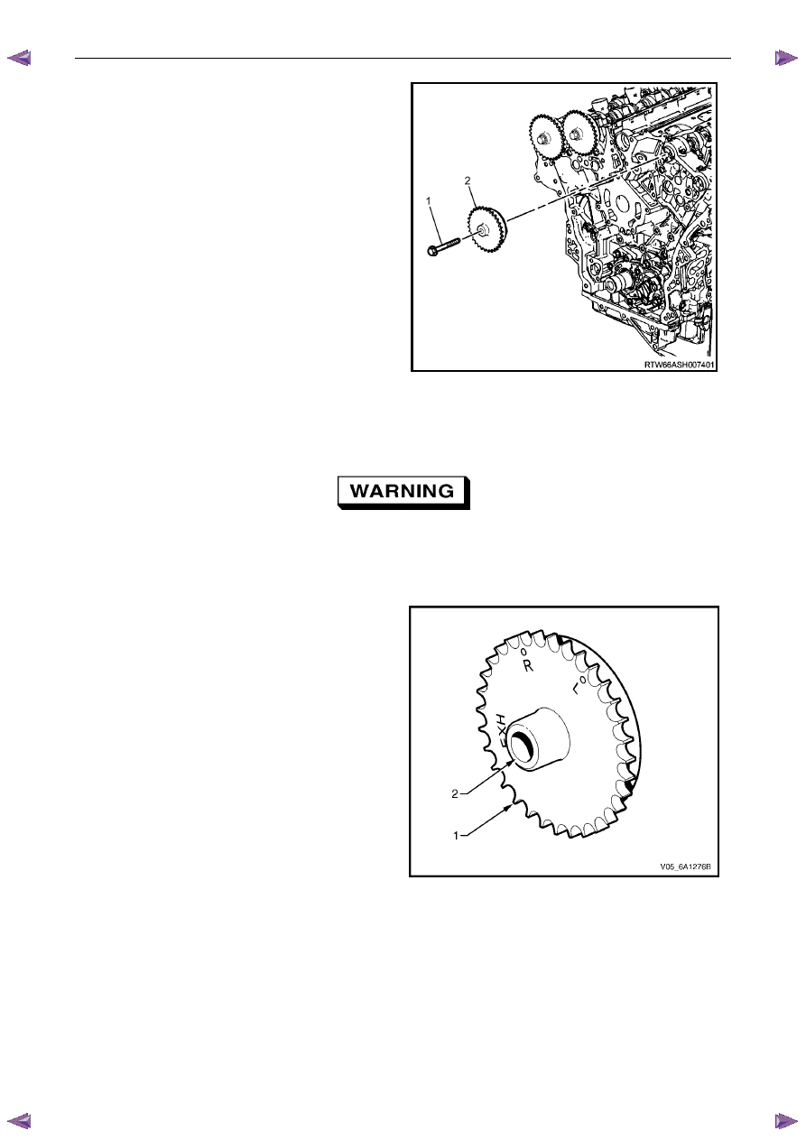
13
Remove the bolt (1) attaching left-hand intake
camshaft sprocket (2) and remove the sprocket.
Figure 6A1 – 235
Clean
1
Clean the exterior of each camshaft sprocket with solvent.
Safety glasses must be worn when using
compressed air.
2
Dry the timing components with compressed air.
Inspect
1
Inspect the front of each sprocket for the following:
•
Sprocket damage (1), and
•
Sprocket bolt seating inner hub damage (2).
Figure 6A1 – 236
Engine Mechanical – V6
Page 6A1–147
2
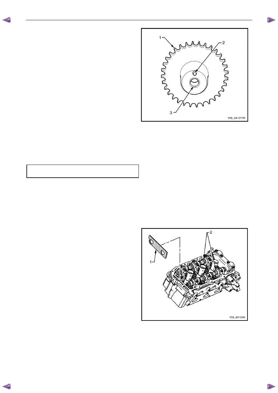
Inspect the back of each sprocket for the following:
•
Sprocket damage (1),
•
Camshaft locating pin damage (2) and,
•
Camshaft seating/sealing inner hub flange
damage (3),
N O T E
These checks apply to both the inlet and
exhaust camshaft sprockets.
Figure 6A1 – 237
Reinstall
Reinstallation of the camshaft sprockets is the reverse of the removal procedure, noting the following:
1
Align the sprockets and timing chain with the marks made during removal.
2
Tighten the camshaft sprocket bolts to the correct torque specification.
Camshaft sprocket attaching
bolt torque specification . . . . . . ..49.0 – 67.0 Nm
3
Remove the timing chain retention tools.
3.19 Camshaft
Remove
Right-hand Side
1
Remove the right-hand cylinder head camshaft sprockets, refer to 3.18
Camshaft Sprocket.
2
Remove the Tool No. EN-46105 – 1 (1) from the right-
hand cylinder head camshafts (2).
N O T E
Tool No. EN-46105 was installed as part of the
right-hand cylinder head camshaft sprocket
removal procedure.
Figure 6A1 – 238
Engine Mechanical – V6
Page 6A1–148
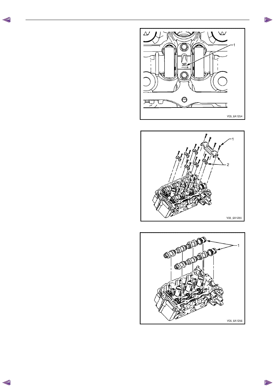
3
Observe the markings (1) on the bearing caps. Each
bearing cap is marked to identify its location. The
markings have the following meanings:
•
The raised feature must always be oriented
toward the centre of the cylinder head.
•
An I indicates the intake camshaft.
•
An E indicates the exhaust camshaft.
•
The number indicates the journal position from
the front of the engine.
Figure 6A1 – 239
4
Remove the camshaft bearing cap bolts (1) and
caps (2).
Figure 6A1 – 240
5
Remove the camshafts (1).
Figure 6A1 – 241
Нет комментариевНе стесняйтесь поделиться с нами вашим ценным мнением.
Текст