Isuzu KB P190. Manual — part 655

Engine Mechanical – V6
Page 6A1–141
Reassemble
CAUTION
As there are no serviceable components
within the oil pump, a disassembled oil pump
must be replaced.
Reinstall
1
Align the oil pump gerotor with the crankshaft flats
and fit the oil pump assembly to the engine block.
2
Align the pump body (2) with the mounting holes in
the cylinder block.
3
Install the oil pump bolt (1), three places, and tighten
to the correct torque specification.
4
Install the primary timing chain, refer to 3.16
Timing Chains, Tensioners, Shoes and Guides.
Oil pump attaching bolt torque
specification . . . . . . . . . . . 20.0 – 26.0 Nm
Figure 6A1 – 223
3.18 Camshaft
Sprocket
CAUTION
Setting the camshaft timing is required
whenever the camshaft drive system is
disturbed to ensure the relationship between
any chain and sprocket is not lost. Even when
only one sprocket is involved, multiple
crankshaft rotations will not produce
conditions where correct timing can be
confirmed.
If required, follow the Left-hand Secondary
Camshaft Chain Components reinstallation
procedure to reset the camshaft timing.
Remove
Right-hand Side
1
Remove the right-hand camshaft cover, refer to 3.12
Camshaft Cover.
2
Remove the camshaft position sensors, refer to 6C1-3 Engine Management – Service Operations.
3
Remove the camshaft position actuator solenoids, refer to 6C1-3 Engine Management – V6 – Service Operations.
4
Remove the crankshaft balancer assembly, refer to 3.13 Crankshaft Balancer Assembly.
Engine Mechanical – V6
Page 6A1–142
5
Install the crankshaft rotation socket Tool No.
EN-46111 onto the crankshaft.
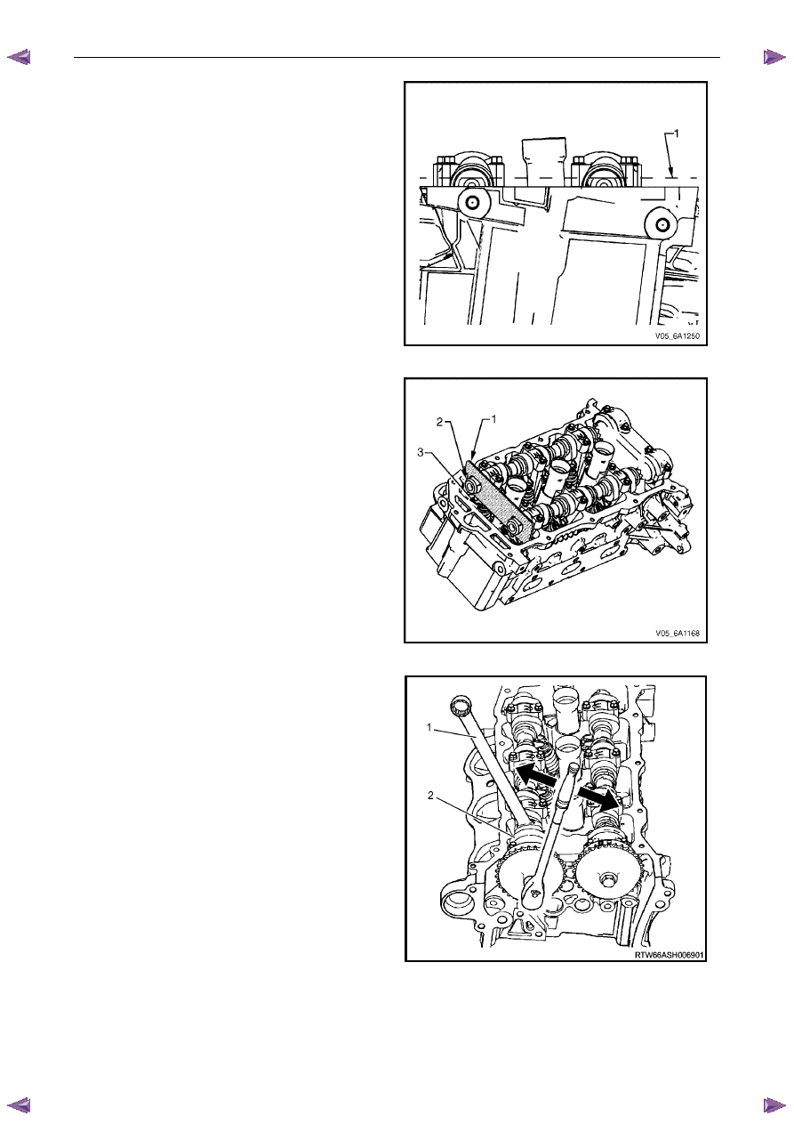
6
Rotate the crankshaft until the camshafts are in a
neutral low tension position. The camshaft flats will be
parallel with the camshaft cover rail (1).
Figure 6A1 – 224
7
Install Tool No. EN-46105 – 1 (1) onto the rear of the
right-hand cylinder head (3) camshafts (2).
Figure 6A1 – 225
8
Loosen the camshaft sprocket bolt.
N O T E
• Use an open-end spanner (1) at the
camshaft hex (2) to prevent camshaft/engine
rotation.
• Do not remove the camshaft sprocket bolt at
this time.
• If you have already removed the camshaft
timing chain proceed to step 12
Figure 6A1 – 226
Engine Mechanical – V6
Page 6A1–143
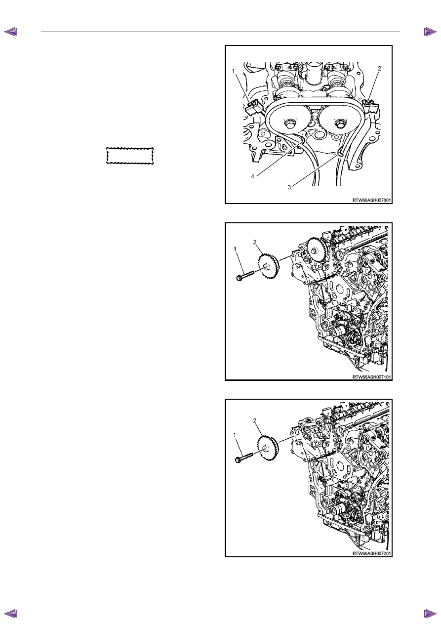
9
Install Tool No. EN-46108 (1 and 2) to retain the
timing chain (3 and 4).
10
Firmly tighten the wing nuts of Tool No. EN-46108.
11
Mark the timing chain and the respective location on
both camshaft sprocket.
N O T E
Ensure the camshaft timing chain and the
camshaft sprocket are marked for correct
reassembly.
CAUTION
Ensure the tips of Tool No.
EN-46108 are fully engaged into the timing
chain and the wing nuts are tight and the
timing chain is taught.
Figure 6A1 – 227
12
Remove the bolt (1) attaching the right-hand exhaust
camshaft sprocket (2) and remove the sprocket.
Figure 6A1 – 228
13
Remove the bolt (1) attaching right-hand intake
camshaft sprocket (2) and remove the sprocket.
Figure 6A1 – 229

Engine Mechanical – V6
Page 6A1–144
Left-hand Side
1
Remove the left-hand camshaft cover, refer to 3.12
Camshaft Cover.
2
Remove the camshaft position sensors, refer to 6C1-3 Engine Management – V6 – Service Operations.
3
Remove the camshaft position actuator solenoids, refer to 6C1-3 Engine Management – V6 – Service Operations.
4
Remove the crankshaft balancer assembly, refer to 3.13 Crankshaft Balancer Assembly.
5
Install the crankshaft rotation socket Tool No.
EN-46111 onto the crankshaft.
6
Rotate the crankshaft until the camshafts are in a
neutral low tension position. The camshaft flats will be
parallel with the camshaft cover rail (1).
Figure 6A1 – 230
7
Install Tool No. EN-46105 – 1 (1) onto the rear of the
left-hand cylinder head camshafts (2).
Figure 6A1 – 231
Нет комментариевНе стесняйтесь поделиться с нами вашим ценным мнением.
Текст