Isuzu KB P190. Manual — part 494
ENGINE CONTROL SYSTEM (4JK1/4JJ1) 6E-359
Mass Air Flow (MAF) Sensor
The MAF sensor is an air flow meter that measures the
amount of air that enters the engine. It is fitted between
the air cleaner and turbocharger. A small quantity of air
that enters the engine indicates deceleration or idle
speed. A large quantity of air that enters the engine
indicates acceleration or a high load condition. The
MAF sensor assembly consists of a MAF sensor
element and an intake air temperature (IAT) sensor that
are both exposed to the air flow to be measured. The
MAF sensor element measures the partial air mass
through a measurement duct on the sensor housing.
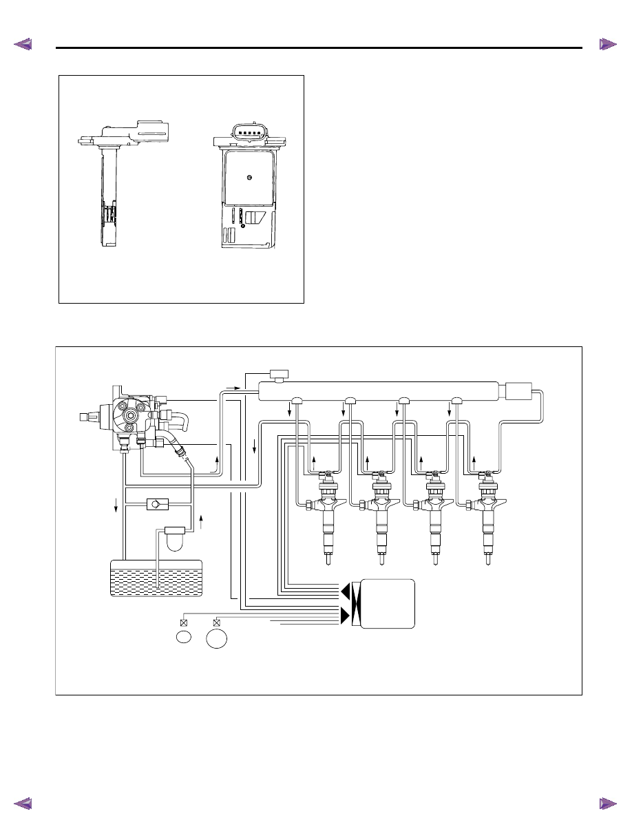
Fuel System Description
The common rail system uses a type of accumulator
chamber called the fuel rail to store pressurized fuel,
and injectors that contain electronically controlled
solenoid valves to spray the pressurized fuel in the
combustion chambers. The injection system (injection
pressure, injection rate, and injection timing) is
controlled by the ECM, and therefore the common rail
system can be controlled independently, free from the
influence of engine speed and load. This ensures a
stable injection pressure at all time, particularly in the
low engine speed range, so that black smoke specific
to diesel engines generated during vehicle starting or
acceleration can be reduced dramatically. As a result,
exhaust gas emissions are clear and reduced, and
higher output is achieved.
AAW46ESH001401
RTW76EMF000401
Supply pump
One-way valve
Fuel tank
Fuel filter
Camshaft
position
sensor
Crankshaft
position
sensor
Various sensors
(accelerator position sensor, coolant temperature,
mass air flow, etc.)
Injectors
Pressure sensor
Fuel rail
Pressure
limiter valve
ECM
6E-360 ENGINE CONTROL SYSTEM (4JK1/4JJ1)
1. High Pressure Control
• Enables high pressure injection from low engine
speed range.
• Optimizes control to minimize particulate matter
and NOx emissions.
2. Injection Timing Control
• Enables finely tuned optimized control in
accordance with running conditions.
3. Injection Rate Control
• Pilot injection control that performs a small amount
of injection before main injection.
The fuel rail system consists primarily of a fuel supply
pump, fuel rail, injectors, and ECM.
Fuel System Component Description
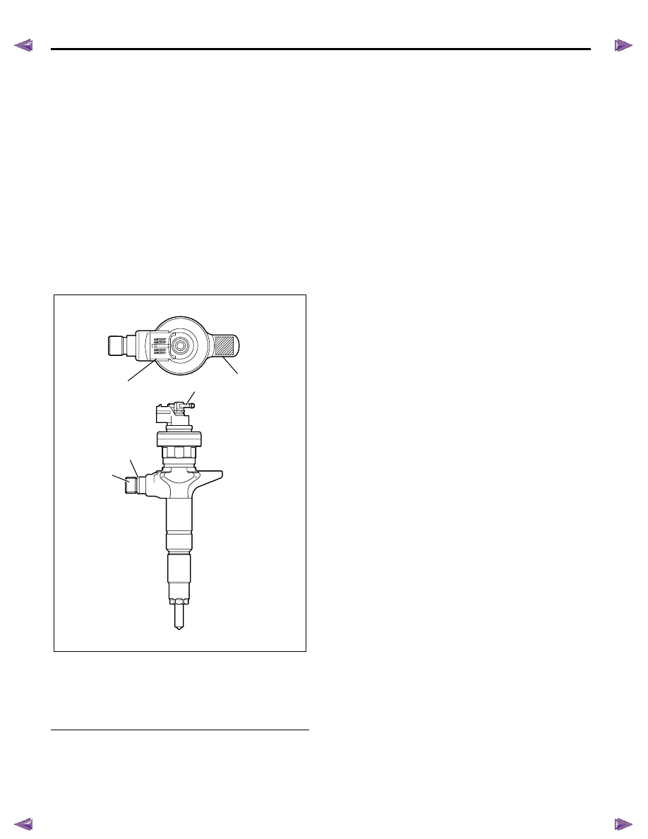
Injector
Legend
1. Fuel injector ID code
2. Leak off pipe
3. Two dimensional barcode
4. Port for mounting the injection pipe
5. O-ring
Electronic control type injectors controlled by the ECM
are used. Compared with conventional injection
nozzles, a command piston, solenoid valve, etc. are
added.
ID codes displaying various injector characteristic are
laser marked on the connector housing, and ID codes
showing these in numeric form (24 alphanumeric
figures). This system uses fuel injector flow rate
information (ID codes) to optimize injection quantity
control. When an injector is newly installed in a vehicle,
it is necessary to input the ID codes in the ECM.
QR (Quick Response) codes or fuel injector flow rate
(ID codes) have been adopted to enhance the injection
quantity precision of the injectors. The adoption of
codes enables injection quantity dispersion control
throughout all pressure ranges, contributing to
improvement in combustion efficiency and reduction in
exhaust gas emissions.
RTW56EMH000101
2
3
1
4
5
ENGINE CONTROL SYSTEM (4JK1/4JJ1) 6E-361
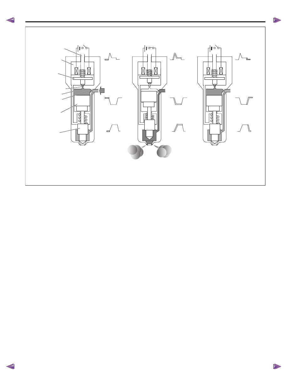
1) Non-injection state
The two way valve (TWV) closes the outlet orifice by
means of a spring force, when no current is supplied
from the ECM to the solenoid. At this time, the fuel
pressure applied to the nozzle leading end is equal to
the fuel pressure applied to the control chamber
through the inlet orifice. As for the force competition in
this state, the pressure on the command piston upper
surface + nozzle spring force defeat the pressure on
the nozzle leading end, and consequently the nozzle is
pushed downward to close the injection holes.
2) Injection start
The TWV is pulled up to open the outlet orifice, and
thus the fuel leaks toward the return port, when the
current is supplied from the ECM to the solenoid. As a
result, the nozzle is pushed up together with the
command piston by the fuel pressure applied to the
nozzle leading end, and then the nozzle injection holes
open to inject the fuel.
3) Injection end
The TWV lowers to close the outlet orifice, when the
ECM shuts off a current supply to the solenoid. As a
result, the fuel cannot leak from the control chamber,
and thus the fuel pressure in the control chamber rises
abruptly and then the nozzle is pushed down by the
command piston to close the nozzle injection holes,
resulting in the end of fuel injection.
RTW76EMF000601
No injection
Injection rate
Pressure in
control chamber
Pressure in
control chamber
Pressure in
control chamber
Driving current
Driving current
Driving current
Injection rate
Injection
Injection end
Solenoid
Outlet orifice
Inlet orifice
Command piston
Nozzle
From fuel rail
TWV
Return port
Control chamber
6E-362 ENGINE CONTROL SYSTEM (4JK1/4JJ1)
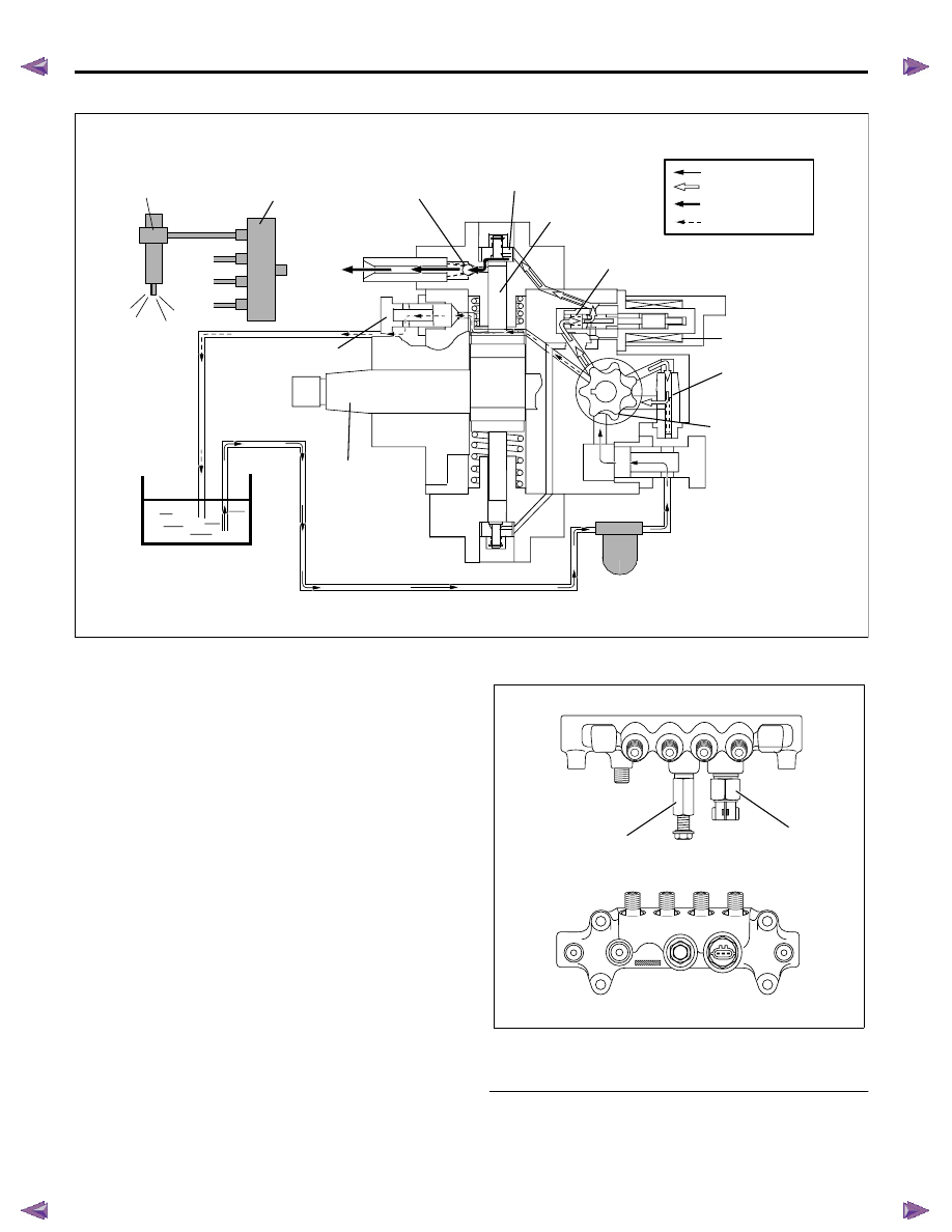
Fuel Supply Pump
The fuel supply pump is the heart of the common rail
type electronic fuel injection system. The fuel supply
pump is installed at the same location as the
conventional injection type pump, which spins at a 1 to
1 ratio of fuel supply pump to crankshaft speed. A fuel
rail pressure (FRP) regulator and fuel temperature
sensor are part of the fuel supply pump assembly.
Fuel is drawn from the fuel tank via the fuel supply
pump by the use of an internal feed pump (trochoid
type). This feed pump pumps fuel into a 2-plunger
chamber also internal to the fuel supply pump. Fuel into
this chamber is regulated by the FRP regulator solely
controlled by current supplied from the ECM. No
current to the solenoid results in maximum fuel flow
whereas full current to the solenoid produces no fuel
flow. As the engine spins, these two plungers produce
high pressure in the fuel rail. Since the ECM controls
the flow of fuel into this 2-plunger chamber, it therefore
controls the quantity and pressure of the fuel supply to
the fuel rail. This optimizes performance, improves
economy and reduces NOx emissions.
Fuel Rail (Common Rail)
Legend
1. Pressure limiter valve
2. Fuel rail pressure (FRP) sensor
RTW76EMF000201
Suction pressure
Feed pressure
Return pressure
High pressure
Fuel rail
Injector
Delivery valve
Cuction valve
Plunger
Fuel inlet
Regulation valve
Driveshaft
Fuel overflow
Feed pump
Return spring
Fuel tank
Fuel filter
Return
Suction
FRP regulator
RTW76ESH002001
1
2
Нет комментариевНе стесняйтесь поделиться с нами вашим ценным мнением.
Текст