Isuzu KB P190. Manual — part 492
ENGINE CONTROL SYSTEM (4JK1/4JJ1) 6E-351
Notice: If the ECM is replaced to new one, VIN does
not displayed. Input correct VIN reading from stamped
VIN or affixed VIN plate on the vehicle. If the ECM from
another vehicle is installed, input correct VIN by same
way.
g. Highlight Engine on the Select System Type
screen, then click "Next", if on-screen
instruction displayed.
h. Complete the following information based on
the service ID plate on the Validate Vehicle
Data screen until "Next" is highlighted, then
click "Next".
• Model
• Model year
• Engine type
• Model designator
• Destination code
• Transmission type
i. Verify your selection on the Summary screen.
Notice: Refer to Service Bulletin and Description
column before service programming is performed if the
bulletins are listed along with the calibration files.
Notice: Select Cancel if you receive a message stating
that the calibration selected is already the current
calibration in the ECM and reprogramming with the
same download is not allowed.
j. Click "Reprog".
k. The Transfer Data screen will appear until the
progress bar reaches 100%.
5. Close the application and return to the TIS
application selection screen after the download is
completed.
6. Turn OFF the scan tool and disconnect from the
terminal.
7. Transfer the data from the scan tool to the ECM
using the following procedure:
a. Install a scan tool.
b. Turn ON the ignition, with the engine OFF.
c. Select Service Programming System (SPS) >
Program ECU.
d. Turn OFF all accessories and press "Continue".
e. Programming in Process will appear until the
progress bar reaches 100%.
Notice: Some warning lamp may turn ON or blink while
programming the ECM since communication between
the ECM and other modules are interrupted. Clear DTC
in any module after programming.
f. Press "Continue" and exit the program after the
scan tool displays "Programming Was
Successful".
8. Turn OFF the ignition.
9. Turn OFF the scan tool and disconnect from the
vehicle.
Service Programming System (SPS) (Pass-
Thru Procedure)
Pass-Thru programming allows the scan tool to remain
connected to the terminal and to the vehicle throughout
the programming process. The vehicle must be in close
proximity to the terminal while using Pass-Thru.
1. Launch the TIS application.
2. Select the Service Programming System at the
main screen.
3. Highlight the following information on the Select
Diagnostic Tool and Programming Process screen,
then click "Next":
• Select Diagnostic Tool-Select Pass - Thru
• Select Programming Process - Identify whether
as existing ECM is being reprogrammed or an
ECM is being replaced with a new one.
• Select ECU Location - Vehicle
4. Complete all vehicle data on the Preparing for
Communication/ Determine Vehicle screen until
"Next" is highlighted, then click "Next".
5. Follow the instruction on the Preparing for
Communication screen, then click "Next".
Notice: In order to reduce the potential for signal loss,
the RS-232 cable should not be more than 25 feet long.
6. Verify the VIN on the Validate Vehicle Identification
Number (VIN) screen, then click "Next".
Notice: If the ECM is replaced to new one, VIN does
not displayed. Input correct VIN reading from stamped
VIN or affixed VIN plate on the vehicle. If the ECM from
another vehicle is installed, input correct VIN by same
way.
7. Highlight Engine on the Select System Type
screen, then click "Next", if on-screen instruction
displayed.
8. Complete the following information based on the
service ID plate on the Validate Vehicle Data
screen until "Next" is highlighted, then click "Next".
• Model
• Model year
• Engine type
• Model designator
• Destination code
• Transmission type
9. Verify your selection on the Summary screen.
Notice: Refer to Service Bulletin and Description
column before service programming is performed if the
bulletins are listed along with the calibration files.
Notice: Select Cancel if you receive a message stating
that the calibration selected is already the current
calibration in the ECM and reprogramming with the
same download is not allowed.
10. Click "Reprog".
6E-352 ENGINE CONTROL SYSTEM (4JK1/4JJ1)
11. The Transfer Data screen will appear until the
progress bar reaches 100%.
Notice: Some warning lamp may turn ON or blink while
programming the ECM since communication between
the ECM and other modules are interrupted. Clear DTC
in any module after programming.
12. Close the application and return to the TIS
application selection screen after the download is
completed.
13. Turn OFF the ignition.
14. Turn OFF the scan tool and disconnect from the
vehicle.
ENGINE CONTROL SYSTEM (4JK1/4JJ1) 6E-353
Description and Operation
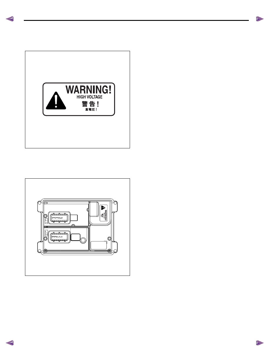
Engine Control Module (ECM) Description
Engine Control Module (ECM) Service Precautions
Important: The symbol ! warns you of an electric shock
hazard. To avoid shock and possible serious injury, DO NOT
touch the terminals. When disconnecting the harness
connectors, always turn OFF the ignition switch or disconnect
the battery cable.
The engine control module (ECM) is designed to
withstand normal current draws associated with vehicle
operation. Avoid overloading any circuit. When testing
for opens and shorts, do not ground or apply voltage to
any of the ECM circuits unless instructed to do so. In
some cases, these circuits should only be tested using
a DMM. The ECM should remain connected to the
ECM harness.
The ECM is located inside of engine compartment via
mounting bracket and is behind air cleaner case. The
ECM mainly controls the following.
• The fuel system control
• The exhaust gas recirculation (EGR) system
control
• The preheating (glow) system control
• The A/C compressor control
• The immobilizer control
• On-board diagnostics for engine control
The ECM constantly observes the information from
various sensors. The ECM controls the systems that
affect vehicle performance. The ECM performs the
diagnostic function of the system. The ECM can
recognize operational problems, alert the driver
through the malfunction indicator lamp (MIL), and store
diagnostic trouble codes (DTCs). DTCs identify the
system faults to aid the technician in making repairs.
RTW56ESH000201
RTW56ESH004401
6E-354 ENGINE CONTROL SYSTEM (4JK1/4JJ1)
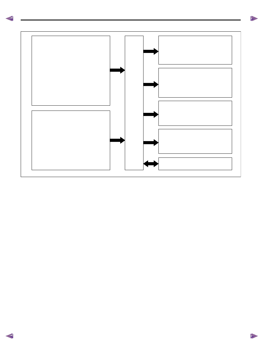
ECM Input & Output
ECM Voltage Description
The ECM supplies a buffered voltage to various
switches and sensors. The ECM can do this because
resistance in the ECM is so high in value that a test
lamp may not illuminate when connected to the circuit.
An ordinary shop voltmeter may not give an accurate
reading because the voltmeter input impedance is too
low. Use a 10-megaohm input impedance DMM, to
ensure accurate voltage readings. The input and/ or
output devices in the ECM include analog-to-digital
converters, signal buffers, counters, and special
drivers. The ECM controls most components with
electronic switches which complete a ground circuit
when turned ON.
Aftermarket Electrical and Vacuum Equipment
Aftermarket or add-on electrical and vacuum
equipment is defined as any equipment which connects
to the vehicle's electrical or vacuum systems that is
installed on a vehicle after the vehicle leaves the
factory. No allowances have been made in the vehicle
design for this type of equipment. No add-on vacuum
equipment should be added to this vehicle. Add-on
electrical equipment must only be connected to the
vehicle's electrical system at the battery power and
ground. Add-on electrical equipment, even when
installed to these guidelines, may still cause the
powertrain system to malfunction. This may also
include equipment not connected to the vehicle
electrical system such as portable telephones and
audios. Therefore, the first step in diagnosing any
powertrain fault is to eliminate all aftermarket electrical
equipment from the vehicle. After this is done, if the
fault still exists, the fault may be diagnosed in the
normal manner.
RTW76EMF000501
Sensor inputs
·
Intake air temperature (IAT) sensor
·
Mass air flow (MAF) sensor
·
Engine coolant temperature (ECT) sensor
·
Fuel temperature (FT) sensor
·
Barometric pressure (BARO) sensor
·
Boost pressure sensor (High output engine)
·
Accelerator pedal position (APP) sensor
·
EGR position sensor
·
Intake throttle position sensor
·
Crankshaft position (CKP) sensor
·
Camshaft position (CMP) sensor
·
Fuel rail pressure (FRP) sensor
·
Vehicle speed sensor (VSS)
Switch input
·
Ignition switch (ON/start position)
·
Clutch switch (M/T)
·
Brake switch
·
Neutral switch
·
Cruise main switch
·
Cruise cancel switch
·
Cruise resume/ accel. switch
·
Cruise set/ cast switch
·
Fuel filter switch
·
A/C switch
·
Diagnostic request switch
Fuel injection control
·
Fuel rail pressure (FRP) regulator
·
Fuel injector #1
·
Fuel injector #2
·
Fuel injector #3
·
Fuel injector #4
Relay control outputs
·
Glow relay
·
Fuel pump relay
·
Starter cut relay
·
A/C compressor relay
Lamp control
·
Malfunction indicator lamp (MIL)
·
Service vehicle soon (SVS) lamp
·
Glow indicator lamp
·
Fuel filter lamp
Communication
·
Controller area network (CAN)
Actuator control
·
Intake throttle solenoid
·
EGR solenoid
·
Swirl control solenoid
·
Turbocharger nozzle control solenoid
(High output engine)
ECM
Нет комментариевНе стесняйтесь поделиться с нами вашим ценным мнением.
Текст