Isuzu KB P190. Manual — part 1004

7A2-50 TRANSMISSION CONTROL SYSTEM (AW30–40LE)
Action Taken When The DTC Sets
• Control at A/T oil temperature 80
°C (176°F).
• No squat control.
• No slope control.
• No 3rd start mode.
• No line pressure reduction at gear change.
• No coast control.
• No line pressure reduction control at garage.
• No shift solenoid functional failure detection.
• No L-up solenoid functional failure detection.
• Check Trans “ON”.
• DTC
stored.
• MIL request “ON”. (EURO 4 only)
Conditions For Clearing The DTC
• The DTC can be cleared from the TCM history by
using a scan tool.
• The DTC will be cleared from history when the
vehicle has achieved 40 warm-up cycles without a
failure reported.
• After more than 1 second has elapsed after the
ignition key has been turned “ON”, short between
No.11 and No.4 (ground) of DLC (Data Link
Connector). Then, after 1 second, but within 6
seconds, discontinue shorting.
Diagnostic Aids
• Inspect the wiring for poor electrical connection at the
TCM. Look for possible bent, backed out, deformed
or damaged terminals. Check for weak terminal
tension as well. Also check for a chafed wire that
could short to bare metal or other wiring. Inspect for a
broken wire inside the insulation.
• When diagnosing for a possible intermittent short or
open condition, move the wiring harness while
observing test equipment for a change.
• Check oil temperature sensor for proper mounting
and adjustment.
Circuit/System Testing DTC P0712
Step Action Value(s)
YES
NO
1
Was the On-Board Diagnostic (OBD) System Check
performed?
— Go
to
Step 2
Go to OBD
System Check
2
Perform the transmission fluid checking procedure.
Refer to checking Transmission Fluid level and
Condition in Automatic Transmission 7A section.
Was the fluid checking procedure performed?
— Go
to
Step 3
Refer to
Checking
Transmission
Fluid level and
Condition in
Automatic
Transmission
(AW30-40LE)
section
3
1. Lift the driving wheels.
2. Start the engine and place the select lever in D
position.
3. Wait for 5 minutes.
Does a scan tool indicate DTC P0712?
— Go
to
Step 4
Refer to
Diagnostic Aids

TRANSMISSION CONTROL SYSTEM (AW30–40LE) 7A2-51
Step Action Value(s)
YES
NO
4
Measure the voltage of the transmission fluid
temperature sensor by the 5-8840-0285-0 DMM.
1. Turn “OFF” the ignition.
2. Disconnect the oil temperature sensor connector.
3. Turn “ON” the ignition., with the engine “OFF”.
4. Connect the 5-8840-0285-0 DMM to the each
terminal of the oil temperature sensor harness
connector E83-2 and E83-1.
Does DMM indicate specified value?
About 5V
Go to Step 5
Go to Step 6
5
Replace the oil temperature sensor.
Is the replacement complete?
— Go
to
Step 8 —
6
Measure the resistance of the wire by the 5-8840-
0285-0 DMM.
1. Turn “OFF” the ignition.
2. Disconnect the TCM connector.
3. Install a jumper wire from terminal E83-1 and E83-
2 on the mission harness.
4. Connect the 5-8840-0285-0 DMM to the each
terminal of the TCM connector C94-11 and C94-
12.
If a problem is found, repair as necessary.
Was the problem found?
Less than
1
Ω
Go to Step 8 Go
to
Step 7
7
Replace the TCM.
Important:
The replacement TCM must be
programmed.
(Refer to SPS for procedure.)
Is the action complete?
— Go
to
Step 8 —
8
1. Reconnect all previously disconnected harness
connector(s).
2. Clear the DTCs with a scan tool.
3. Turn “OFF” the ignition.
4. Start the engine.
5. Operate the vehicle within the Conditions For
Running the DTC. You may also operate the
vehicle within the conditions that you observed
from the Freeze Frame/ Failure Records.
Did the DTC fail this ignition?
— Go
to
Step 2 Go
to
Step 9
9
Observe the stored information, Capture Info with a
scan tool.
Are there any DTCs that you have not diagnosed?
— Go
to
Diagnostic
Trouble Code
(DTC) List
Verify repair
7A2-52 TRANSMISSION CONTROL SYSTEM (AW30–40LE)
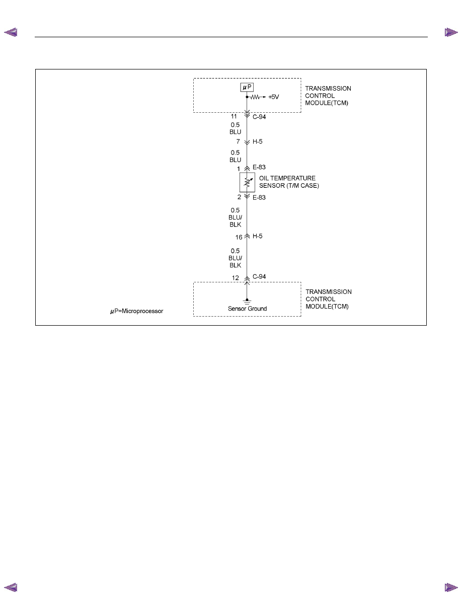
DTC P0713 (Flash Code 16)
RTW77AMF000501
Circuit Description
The oil temperature sensor is a thermistor sensor that is
installed in the transmission case and converts
temperature changes into continuous electric signals,
then outputs them to the Transmission Control Module
(TCM). When the ATF temperature is low, the
resistance of the sensor (thermistor) goes up, so that
the voltage of the TCM signal becomes high.
As the ATF is gradually warmed, the resistance of the
sensor goes down and the voltage becomes low. At the
normal operating ATF temperature (80
°C/176°F) of the
transmission, the voltage of the TCM is about 3.7V.
Condition For Running The DTC
All of the following conditions are met.
(1) Detect the state which the all of the following
conditions are met since ignition “ON”
for
accumulated 15 minutes or more.
• Except P or N position.
• Selector position switch is not detecting failure
or not deciding failure.
• Output revolution is more than 600rpm.
• Output revolution sensor is not detecting failure
or not deciding failure.
(2) Engine coolant temperature ≧ 50
°C (122°F)
(3) Engine coolant temperature signal is not detecting
failure or not deciding failure.
Condition For Setting The DTC
The TCM detects following condition for 12 times
continuously.
• Oil temperature is more than –10
°C (14°F).
Action Taken When The DTC Sets
• Control at A/T oil temperature 80
°C (176°F).
• No squat control.
• No slope control.
• No 3rd start mode.
• No line pressure reduction at gear change.
• No coast control.
• No line pressure reduction control at garage.
• No shift solenoid functional failure detection.

TRANSMISSION CONTROL SYSTEM (AW30–40LE) 7A2-53
• No L-up solenoid functional failure detection.
• Check Trans “ON”.
• DTC
stored.
• MIL request “ON”. (EURO 4 only)
Conditions For Clearing The DTC
• The DTC can be cleared from the TCM history by
using a scan tool.
• The DTC will be cleared from history when the
vehicle has achieved 40 warm-up cycles without a
failure reported.
• After more than 1 second has elapsed after the
ignition key has been turned “ON”, short between
No.11 and No.4 (ground) of DLC (Data Link
Connector). Then, after 1 second, but within 6
seconds, discontinue shorting.
Diagnostic Aids
• Inspect the wiring for poor electrical connection at the
TCM. Look for possible bent, backed out, deformed
or damaged terminals. Check for weak terminal
tension as well. Also check for a chafed wire that
could short to bare metal or other wiring. Inspect for a
broken wire inside the insulation.
• When diagnosing for a possible intermittent short or
open condition, move the wiring harness while
observing test equipment for a change.
• Check oil temperature sensor for proper mounting
and adjustment.
Circuit/System Testing DTC P0713
Step Action Value(s)
YES
NO
1
Was the On-Board Diagnostic (OBD) System Check
performed ?
— Go
to
Step 2
Go to OBD
System check
2
Perform the transmission fluid checking procedure.
Refer to Checking Transmission Fluid Level and
condition Automatic Transmission 7A section.
Was the fluid checking procedure performed?
— Go
to
Step 3
Refer to
checking
Transmission
Fluid Level and
Condition
Automatic
Transmission
(AW30-40LE)
section
3
1. Lift the driving wheels.
2. Start the engine and place the select lever in D
position.
3. Wait for 15 minutes.
Does a scan tool indicate DTC P0713?
— Go
to
Step 4
Refer to
Diagnostic Aids
4
Observe the voltage of the oil temperature sensor on
the Tech 2 data.
1. Turn “OFF” the ignition.
2. Disconnect the oil temperature sensor connector
E-83
3. Install a fused jumper wire from terminal E83-2 to
E83-1 on the transmission harness.
4. Turn “ON” the ignition.
Does a scan tool indicate specified value?
About 0V
Go to Step 5
Go to Step 6
5
Replace the transmission fluid temperature sensor.
If the action complete?
— Go
to
Step 9 —
Нет комментариевНе стесняйтесь поделиться с нами вашим ценным мнением.
Текст