Isuzu KB P190. Manual — part 1005

7A2-54 TRANSMISSION CONTROL SYSTEM (AW30–40LE)
Step Action Value(s)
YES
NO
6
Measure the resistance of wire by the 5-8840-0285-0
DMM.
1. Turn “OFF” the ignition.
2. Disconnect the TCM connector.
3. Install a fused jumper wire between terminals E83-
1 and E83-2 on the transmission harness.
Does DMM indicate specified value?
Less than
1
Ω
Go to Step 8
Go to Step 7
7
An open circuit between TCM from oil temperature
sensor.
Repair the harness.
Is the action complete ?
— Go
to
Step 9 —
8
Replace the TCM
Important: The replacement TCM must be
programmed. (Refer to SPS for procedure.)
Is the action complete?
— Go
to
Step 9 —
9
1. Reconnect all previously disconnected harness
connector(s).
2. Clear the DTCs with a scan tool.
3. Turn “OFF” the ignition.
4. Start the engine.
5. Operate the vehicle within the Conditions For
Running the DTC. You may also operate the
vehicle within the conditions that you observed
from the Freeze Frame/ Failure Records.
Did the DTC fail this ignition?
— Go
to
Step 2 Go
to
Step 10
10
Observe the stored information, Capture Info with a
scan tool.
Are there any DTCs that you have not diagnosed?
— Go
to
Diagnostic
Trouble Code
(DTC) List
Verify repair
TRANSMISSION CONTROL SYSTEM (AW30–40LE) 7A2-55
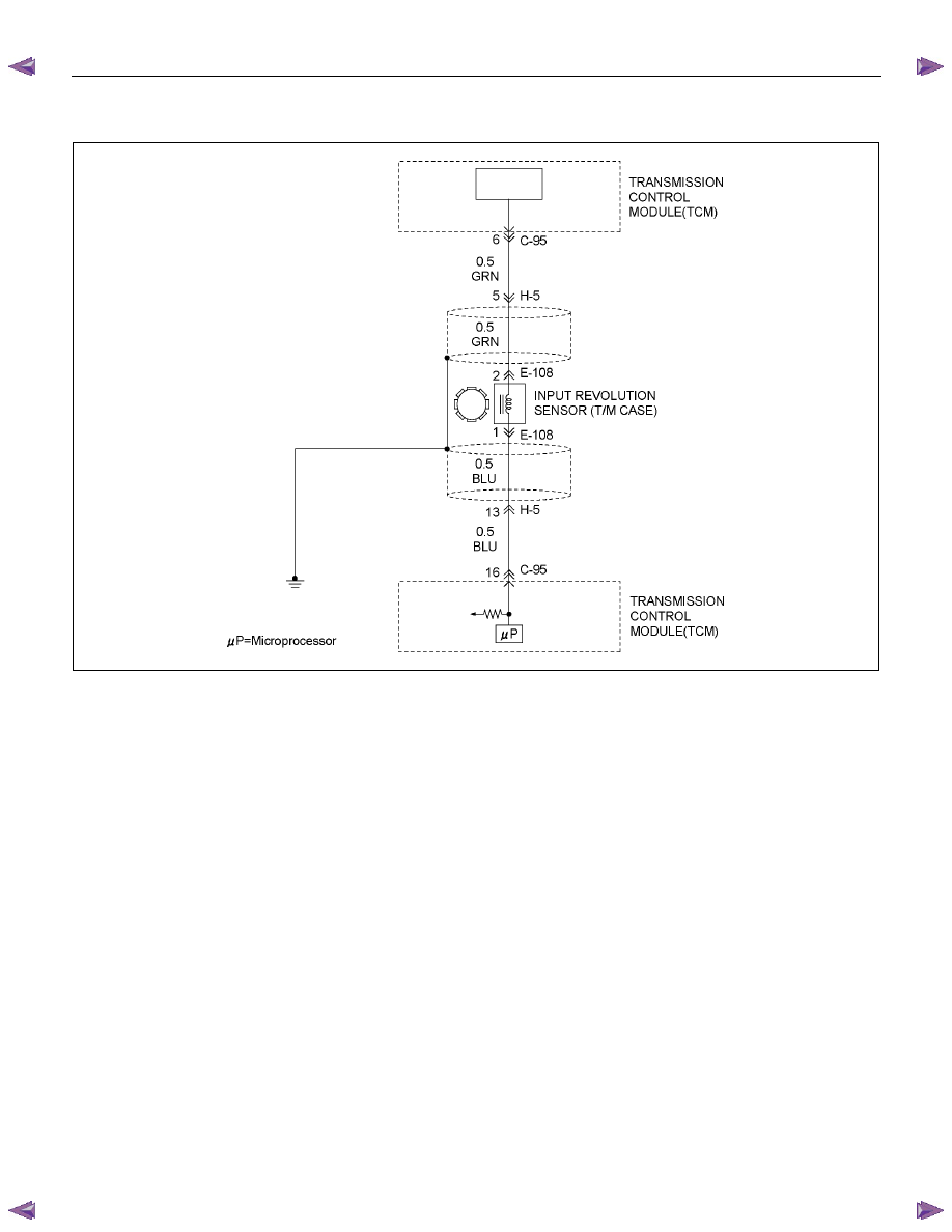
DTC P0717 (Flash Code 14)
RTW77AMF000601
Circuit Description
Input revolution information is provided to TCM by the
input revolution sensor. This sensor is located in the
transmission case.
The input revolution sensor is an electromagnetic pulse
pickup type that generates a speed signal according to
the revolution of the transmission OD direct clutch
drum. As a result, the sensor sends a sine wave signal
(AC) to the TCM, which converts this sine wave signal
(pulse voltage) to a RPM signal.
Condition For Running The DTC
All of the following conditions are met.
(1) All of the following conditions are met for 2
seconds or more continuously.
• The supply voltage is more than 10.2 volts and
less than 15.5 volts.
• DTC U2104 is not detecting failure or not
deciding failure.
• DTC U2105 is not detecting failure or not
deciding failure.
• Engine revolution sensor is not detecting failure
or not deciding failure.
• The engine revolution is more than 550rpm.
(2) Not emergency mode.
(3) All of the following conditions are met.
• Device Control is not operating.
• Disable Normal Communication Service is
receiving enable.
• DTC Clear is not operating.
Condition For Setting The DTC
All of the following conditions are met.
(1) 25 seconds or more passed after changing to the
except P/R/N from P/R/N.
If the following condition is met when 25 seconds
or more passed after changing, it is considered
that 25 seconds or more passed.
• The oil temperature sensor is not detecting
failure or not deciding failure, and also oil
temperature is more than 20
°C (68°F).

7A2-56 TRANSMISSION CONTROL SYSTEM (AW30–40LE)
(2) Select position switches is not detecting failure or
not deciding failure.
(3) Output revolution sensor is not detecting failure or
not deciding failure.
(4) Output revolution is more than 600rpm.
(5) If output signal pulse count is more than 9×500,
any pulse is not detected from input revolution
sensor.
(6) Any pulse is not detected at 2nd from input
revolution sensor after condition (9) is met.
(7) Shift solenoid S1 and Shift solenoid S2 are not
detecting electric failure or not deciding electric
failure.
(8) Shift solenoid S1 and Shift solenoid S2 are not
deciding functional failure.
If the following conditions are not met, keep the
failure detection counter.
(9) 3.5 seconds or more passed after the gear change
signal output.
(10) Not 4th gear.
Action Taken When The DTC Sets
• No
L-up.
• No line pressure reduction control at gear shift.
• No torque reduction control.
• No slope control
• No output revolution sensor failure detection.
• Cancel input revolution condition of the “Condition
For Running The DTC” of system voltage error
detection.
• No shift solenoid failure detection.
• No L-up solenoid failure detection.
• DTC
stored.
• Check Trans "ON".
• MIL request "ON". (EURO 4 only)
Conditions For Clearing The DTC
• The DTC can be cleared from the TCM history by
using a scan tool.
• The DTC will be cleared from history when the
vehicle has achieved 40 warm-up cycles without a
failure reported.
• After more than 1 second has elapsed after the
ignition key has been turned “ON”, short between
No.11 and No.4 (ground) of DLC (Data Link
Connector). Then, after 1 second, but within 6
seconds, discontinue shorting.
Diagnostic Aids
• Inspect the wiring for poor electrical connection at the
TCM. Look for possible bent, backed out, deformed
or damaged terminals. Check for weak terminal
tension as well. Also check for a chafed wire that
could short to bare metal or other wiring.
Inspect for a broken wire inside the insulation.
• When diagnosing for a possible intermittent short or
open condition, move the wiring harness while
observing test equipment for a change.
• Check input speed sensor for proper mounting and
adjustment.
Circuit/System Testing DTC P0717
Step Action Value(s)
YES
NO
1
Was the On-Board Diagnostic (OBD) System check
performed?
— Go
to
Step 2
Go to OBD
system check
2
1. Install a scan tool.
2. Turn on the ignition.
3. Review and record scan tool data.
4. Operate the vehicle within scan tool data.
Does a scan tool indicate DTC P0717?
— Go
to
Step 3
Refer to
Diagnostic Aids

TRANSMISSION CONTROL SYSTEM (AW30–40LE) 7A2-57
Step Action Value(s)
YES
NO
3
Measure voltage of the input revolution sensor by the
5-8840-0285-0 DMM.
1. Turn “ON” the ignition.
2. Engine run.
3. Disconnect the input revolution sensor connector.
4. Measure the voltage between terminals to the input
revolution sensor harness connector E108-1 and
E108-2.
Does DMM indicate specified value?
About 3V
Go to Step 6
Go to Step 4
4
Measure the resistance of wire by the 5-8840-0285-0
DMM.
1. Turn “OFF” the ignition.
2. Disconnect the TCM connector.
3. Connect the input revolution sensor connector.
4.
Measure the resistance between the TCM
connector terminal C95-6 and C95-16.
Does DMM indicate specified value?
560
∼
680
Ω
(20
°C/68°F)
Go to Step 7
Go to Step 5
5
Measure the resistance of input revolution sensor by
the 5-8840-0285-0 DMM.
1. Turn “OFF” the ignition.
2. Disconnect the input revolution sensor connector.
3. Measure the resistance between terminals of input
revolution sensor side connector, E108-1 and
E108-2.
Does DMM indicate specified value?
560
∼
680
Ω
(20
°C/68°F)
Go to Step 8
Go to Step 6
6
Replace the input revolution sensor.
Is the action complete?
— Go
to
Step 9 —
7
Replace the TCM.
Important: The replacement TCM must be
programmed. (Refer to SPS for procedure.)
Is the action complete?
— Go
to
Step 9 —
8
Check the wire between terminal C95-6 and E108-2
or C95-16 and E108-1.
1. Connect the 5-8840-0285-0 DMM to the each of
the TCM connector and input revolution sensor.
If the problem found repair as necessary.
Was the problem found?
— Go
to
Step 9 —
Нет комментариевНе стесняйтесь поделиться с нами вашим ценным мнением.
Текст