Isuzu KB P190. Manual — part 920
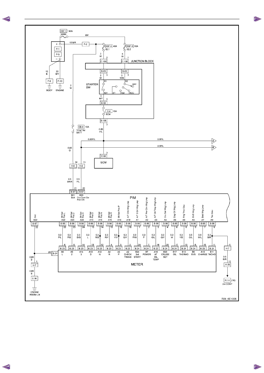
Powertrain Interface Module – V6
Page 6E1–19
Figure 6E1 – 14
Powertrain Interface Module – V6
Page 6E1–20
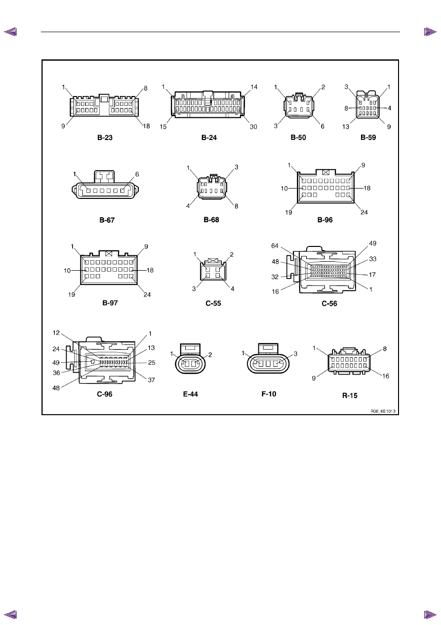
6.2 Connector
Chart
Figure 6E1 – 15
Powertrain Interface Module – V6
Page 6E1–21
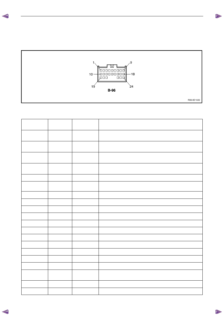
6.3 Connector
Information
PIM Connector Pin Specifications
Pin Description – Connector B-96
Figure 6E1 – 1
Pin No.
Wire Colour
Circuit
Description
Function
1 P/W
A/T 3 Srt Wrg
Lmp
Auto Transmission 3rd Start Warning Lamp
2 P
A/T Pwr Dr
Wrg Lmp
Auto Transmission Power Drive Warning Lamp
3 O/L
A/T Oil Tmp
Wrg Lmp
Auto Transmission Oil Temperature Warning Lamp
4 G/Y
Cru Set Wrg
Lmp
Cruise Set Warning Lamp
5
O/L
SVS Wrg Lmp
Service Vehicle Soon Warning Lamp
6 W
Eng Oil Wrg
Lmp
Engine Oil Pressure Warning Lamp holidays
7
W/L
Batt Wrg Lmp
Battery Charge Warning Lamp
8
Y/B
Eng Tmp Gau
Engine Coolant Gauge
9
B/R
Tac Gau
Tacho Gauge – RWD/4WD (2-4) Control
10 W
Imob
Sig
Immobiliser
11 — —
Not
Connected
12 — —
Not
Connected
13
L
Sft Sel Pos D
Shift Selector Position D
14
R/B
Sft Sel Pos N
Shift Selector Position N
15
R/Y
Sft Sel Pos R
Shift Selector Position R
16
Y/V
Sft Sel Pos P
Shift Selector Position P
17 — —
Not
Connected
18 G/Y
A/T Chk Wrg
Lmp
Auto Transmission Check Warning Lamp
19 — —
Not
Connected
20 — —
Not
Connected
Powertrain Interface Module – V6
Page 6E1–22
Pin No.
Wire Colour
Circuit
Description
Function
21 — —
Not
Connected
22
P/L
Sft Sel Pos L
Shift Selector PRNDL Position L
23
P/B
Sft Sel Pos 2
Shift Selector Position 2
24
B/G
Sft Sel Pos 3
Shift Selector Position 3
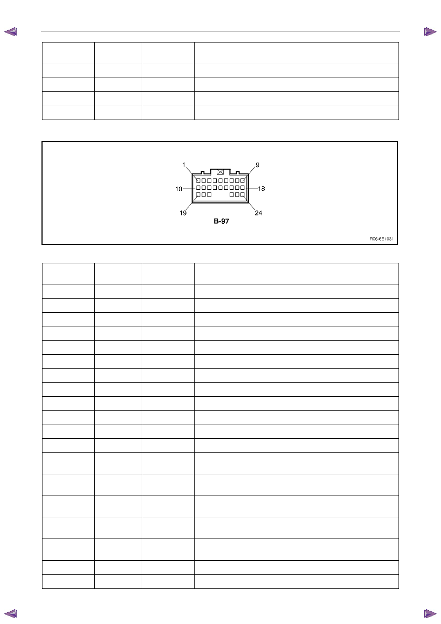
Pin Description – Connector B-97
Figure 6E1 – 2
Pin No.
Wire Colour
Circuit
Description
Function
1
L
TOSS Sen
IND Speed Sensor
2
L/W
Lat G Sen
Lateral G-sensor
3
O
Lat G Sen
Lateral G-sensor
4
B
Lat G Sen
Lateral G-sensor
5 — —
Not
Connected
6 — —
Not
Connected
7 — —
Not
Connected
8 — —
Not
Connected
9 — —
Not
Connected
10
G/W
A/T 3 Srt Sw
Auto Transmission 3rd Start Switch
11
G/R
Thermo AMP
Thermo AMP
12
L/W
2-4 Cont
RWD/4WD (2-4) Control
13 G/W
Cru Cont ON
Lmp
Cruise Control ON Lamp
14 W/G
Cru Cont Main
Sw
Cruise Control Main Switch
15 LG
Cru Cont Set
Sw
Cruise Control Set Switch
16 BR/Y
Cru Cont Res
Sw
Cruise Control Resume Switch
17 GR/G
Cru Cont Can
Sw
Cruise Control Cancel Switch
18
B/W
TOSS Sen
IND Speed Sensor
19 — —
Not
Connected
Нет комментариевНе стесняйтесь поделиться с нами вашим ценным мнением.
Текст