Isuzu KB P190. Manual — part 1294
8A-238 ELECTRICAL-BODY AND CHASSIS
Bulb
Be absolutely sure that the side turn light bulb is correctly
installed.
This will prevent a poor contact and an open circuit.
A Type
RTW780SH002101
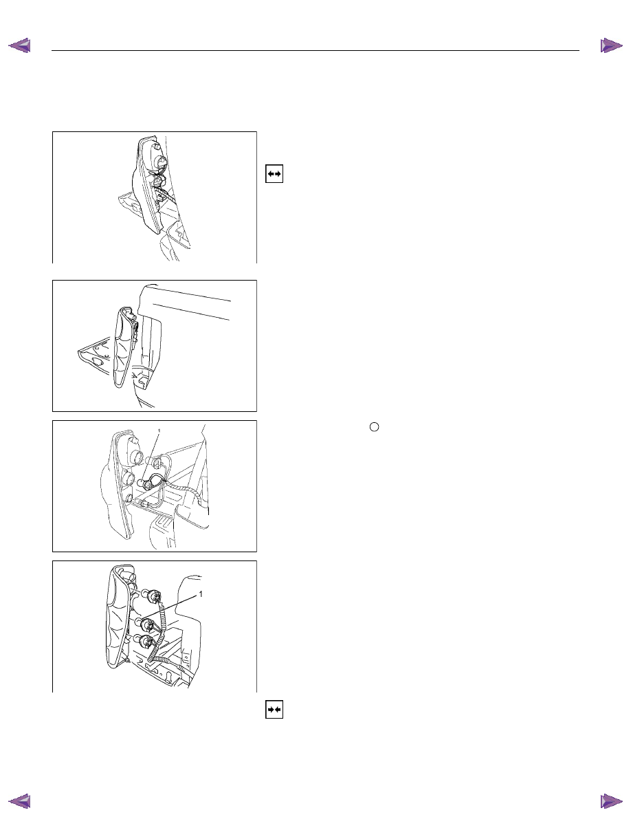
REAR COMBINATION LIGHT
Turn Signal Light
Removal
1. Open the tail gate.
2. Remove the screws.
3. Remove the rear combination light assembly.
B Type
RTW580SH000401
A Type
RTW780SH001301
4. Turn the bulb
1
counterclockwise to remove it.
B Type
RTW78ASH002501
Installation
Follow the removal procedure in the reverse order to install the
rear combination light.
Pay close attention to the important points mentioned in the
following paragraphs.
ELECTRICAL-BODY AND CHASSIS 8A-239
Bulb
Be absolutely sure that the rear combination light bulb is
correctly installed.
This will prevent a poor contact and an open circuit.
RTW780SH000901
This illustration is based on RHD model
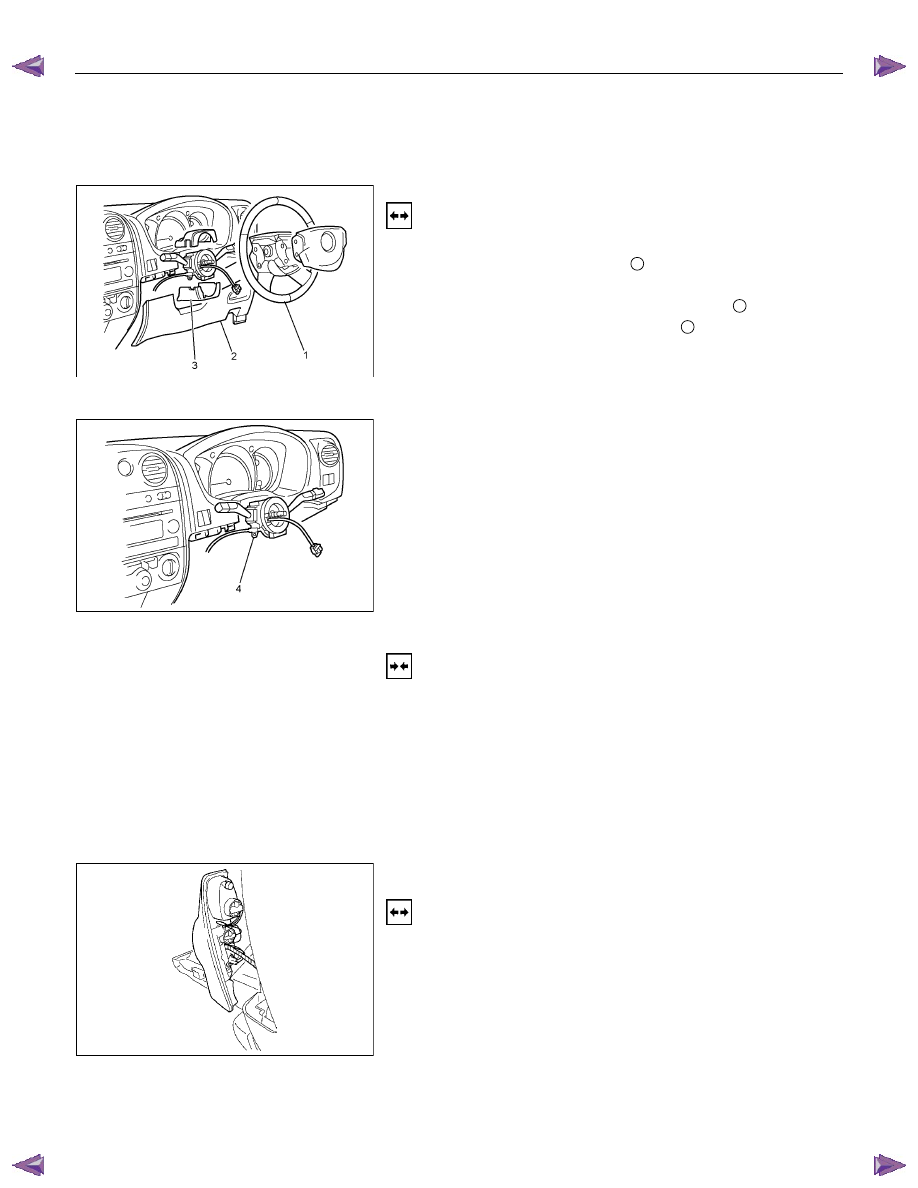
TURN SIGNAL LIGHT SWITCH
Removal
1. Disconnect the battery ground cable.
2. Remove the steering wheel
1
.
Refer to the “STEERING” Section of this Manual.
3. Remove the instruments panel lower cover
2
.
4. Remove the steering column cover
3
.
RTW780SH001001
This illustration is based on RHD model
5. Disconnect the connector.
6. Remove the turn signal switch from the steering shaft.
Installation
Follow the removal procedure in the reverse order to install the
turn signal switch (lever).
Pay close attention to the important points mentioned in the
following paragraphs.
Connector
Be absolutely sure that the turn signal switch connector is
securely connected.
This will prevent a poor contact and at an open circuit.
A Type
RTW780SH002101
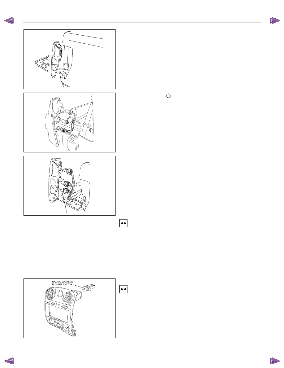
REAR COMBINATION LIGHT
Backup Light
Removal
1. Open the rear gate.
2. Remove the screws.
3. Remove the rear combination light assembly.
8A-240 ELECTRICAL-BODY AND CHASSIS
B Type
RTW580SH000401
A Type
RTW780SH001401
4. Turn the bulb
1
counterclockwise to remove it.
B Type
RTW78ASH002601
Installation
Follow the removal procedure in the reverse order to install the
rear combination light.
Pay close attention to the important points mentioned in the
following paragraphs.
Bulbs
Be absolutely sure that each bulb is correctly installed.
This will prevent a poor contact and an open circuit.
RTW780SH001501
This illustration is based on RHD model
HAZARD WARNING FLASHER SWITCH
Removal
1. Disconnect the battery ground cable.
2. Instrument Panel Cluster Assembly
• Refer to Section 10 “BODY” for instrument panel cluster
assembly removal steps.
3. Hazard Warning Switch
• Disconnect the switch connector.
• To remove the switch, push the lock from the back side
of the cluster assembly.
ELECTRICAL-BODY AND CHASSIS 8A-241
Installation
To install, follow the removal procedure in the reverse order.
Connector
Be absolutely sure that the hazard warning flasher switch
connector is securely connected.
This will prevent a poor contact and an open circuit.
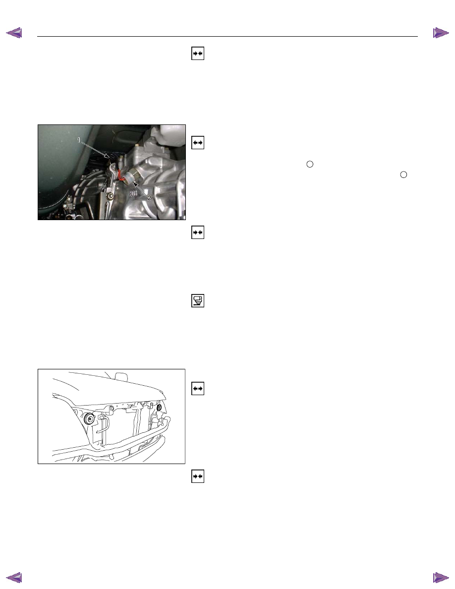
BACKUP LIGHT SWITCH
Removal
1. Disconnect the battery ground cable.
2. Disconnect the connector
1
.
3. Remove the backup light switch from the transmission
2
.
Installation
Follow the removal procedure in the reverse order to install the
backup light switch.
Pay close attention to the important points mentioned in the
following paragraphs.
Backup Light Switch Threads
Apply liquid gasket to the threaded portion and install the
backup light switch.
Connector
Be absolutely sure that the backup light connector is securely
connected.
This will prevent a poor contact and an open circuit.
HORN
Removal
1. Remove the radiator grille.
Refer to the “HEADLIGHT” removal procedure.
2. Loosen the horn bolt.
3. Disconnect the horn connector.
Installation
Follow the removal procedure in the reverse order to install the
horn.
Pay close attention to the important point mentioned in the
following paragraphs.
Connector
Be absolutely sure the horn connector is securely connected.
This will prevent a poor contact and open circuit.
Нет комментариевНе стесняйтесь поделиться с нами вашим ценным мнением.
Текст