Isuzu KB P190. Manual — part 1295

8A-242 ELECTRICAL-BODY AND CHASSIS
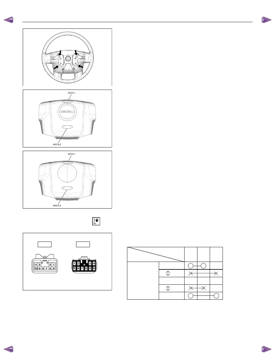
HORN SWITCH
Removal
1. Disable the SRS (Refer to “Disabling the SRS” in Section
9A).
2. Insertion hole for pin push bar at below the steering wheel
indicated arrow.
RTW78ASH001901
3. Check the position of the pins in the holes before insert the
pin push bar. Push the pin in the direction of the arrow.
4. Push the four pins using the
φ5∼6 bar for cancel the lock on
the four pins.
RTW78ASH002201
5. Disconnect the SRS air bag connector
1
and horn lead
connector
2
and remove the air bag assembly.
6. Remove the horn switch.
RTW78ASH002401
Installation
1. Connect the SRS bag connector and horn lead connector.
2. Align each snap stud of the driver air bag to the hole in the
steering wheel.
ELECTRICAL-BODY AND CHASSIS 8A-243
RTW78ASH002001
A Type
RTW78ASH002101
3. Push the horn switch area1 and area-2. At that time check
the audible noise from each snap stud. (Should be no noise
present)
4. Enable the SRS (Refer to “Enabling the SRS” in Section
9A).
B Type
RTW780SH003101
INSPECTION AND REPAIR
Switch side
Harness side
B60
B60
TURN SIGNAL SWITCH
Lighting Switch Connections
Terminal No.
SW position
5 6 7
Left
Neutral
Right
Turning
direction
8A-244 ELECTRICAL-BODY AND CHASSIS
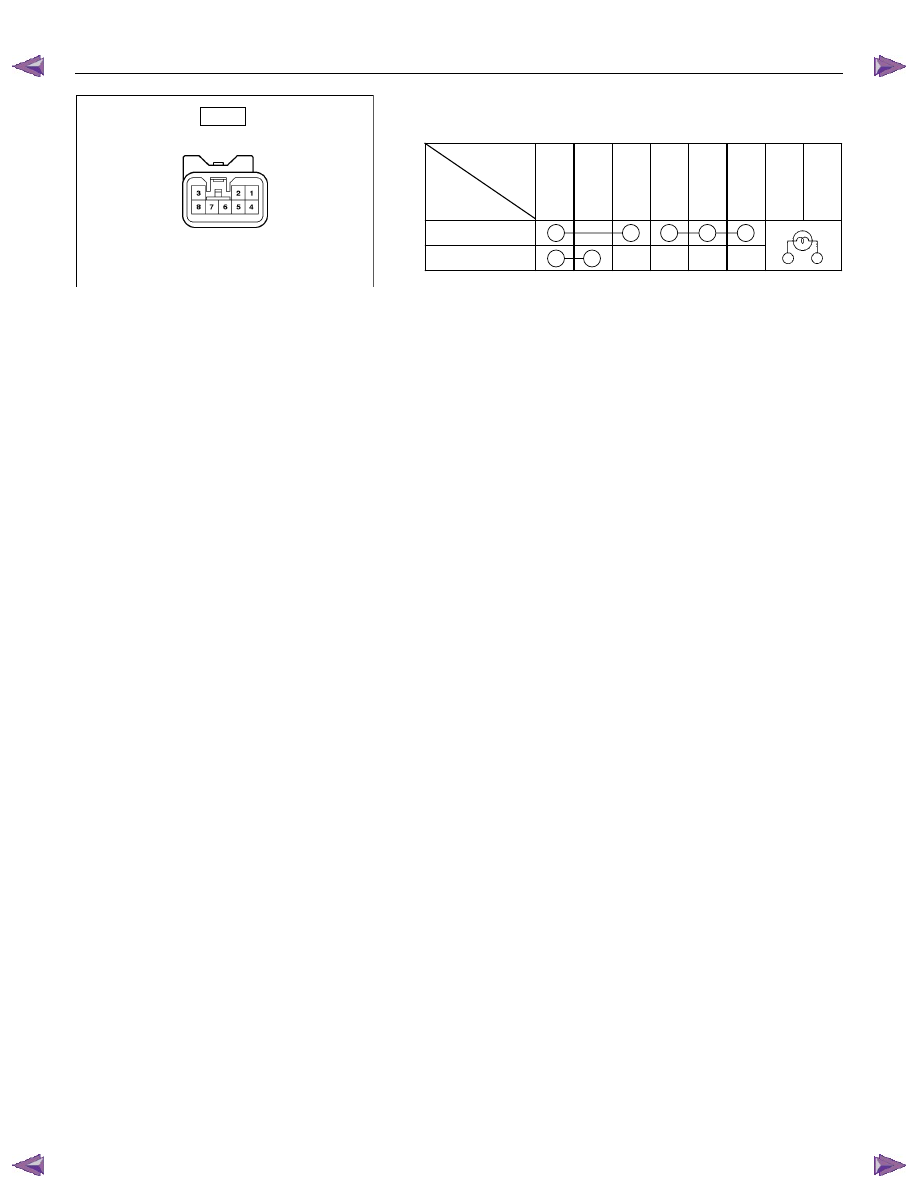
Switch side
B16
HAZARD WARNING FLASHER SWITCH
Hazard Warning Flasher Switch Connections
Terminal
No.
SW position
4
6
5
3
2
1
7
8
ON
OFF
ELECTRICAL-BODY AND CHASSIS 8A-245
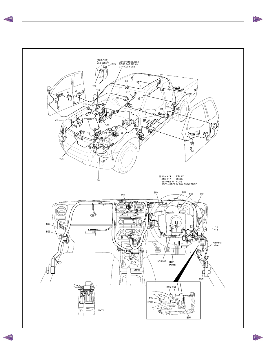
DOME LIGHT, SPOTLIGHT, MAP LIGHT AND WARNING BUZZER
PARTS LOCATION (RHD)
RTW78AXF037901 & RTW78AXF044101
Нет комментариевНе стесняйтесь поделиться с нами вашим ценным мнением.
Текст