Isuzu KB P190. Manual — part 668

Engine Mechanical – V6
Page 6A1–193
Figure 6A1 – 338
50
Unplug the connector from the oil level sensor (1).
51
Remove the attaching bolt (2) holding the ground
cable to the engine block.
Figure 6A1 – 339
52
Remove the accessory drive belt using a socket
wrench (1), to reduce tension rotate the drive belt
tensioner (2) clockwise, then while holding the
tensioner in the reduced tension position, remove the
accessory drive belt (3).
Figure 6A1 – 340
53
Remove the power steering pump bolts (two places),
remove the pump (1) from the mounting bracket and
disconnect the power steering hoses (two places)
from the pump body.
N O T E
Plug the open ends of the power steering hoses
to prevent the ingress of contaminants.
Figure 6A1 – 341

Engine Mechanical – V6
Page 6A1–194
54
Remove the power steering pump bracket mounting
bolts (three places) then remove the pump bracket
(1).
Figure 6A1 – 342
55
Release the lower radiator hose clamp (1) and
remove the lower hose from the coolant pipe (2).
Figure 6A1 – 343
56
Release the upper radiator hose clamp (1) and
remove the upper hose from the coolant pipe (2).
Figure 6A1 – 344
Engine Mechanical – V6
Page 6A1–195
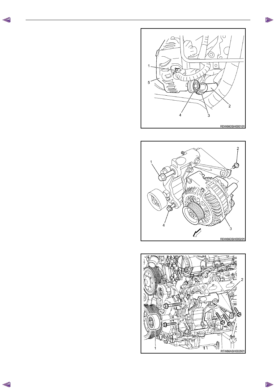
57
Unclip and remove the generator wiring harness
connector (1), Remove battery connection attaching
nut (4), and remove the battery harness cable (2)
from the connection stud.
Figure 6A1 – 345
58
Remove the generator attaching bolts (1, 2, and 4)
three places, then remove the generator (3) from the
mounting bracket.
Figure 6A1 – 346
59
Remove the idler pulley attaching bolt and remove the
idler pulley (1).
60
Remove the generator bracket attaching bolts, five
places, and remove the generator mounting bracket
(2).
Figure 6A1 – 347
Engine Mechanical – V6
Page 6A1–196
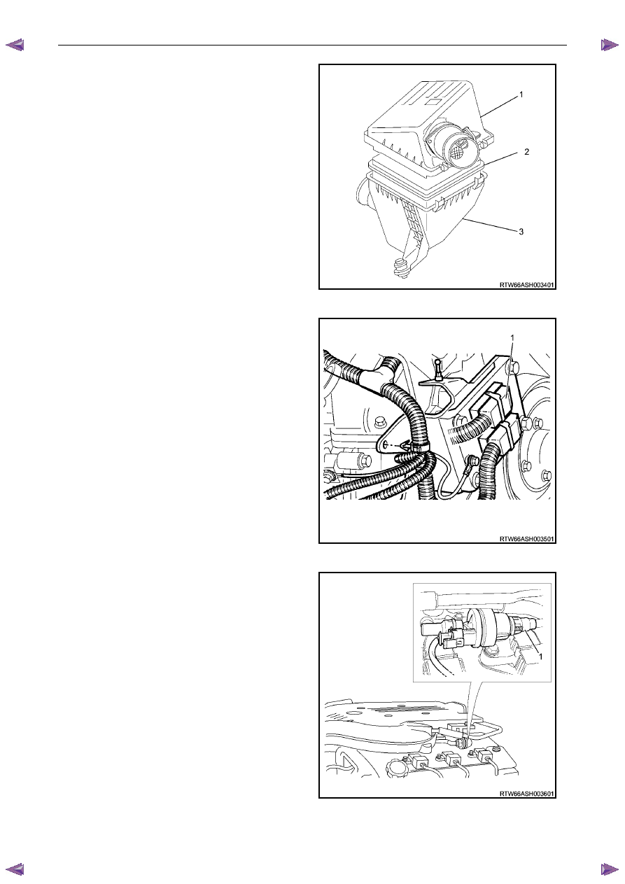
61
Remove the air cleaner cover assembly including the
MAF sensor assembly (1).
62
Remove the air cleaner filter (2) from the air cleaner
body assembly (3).
Figure 6A1 – 348
63
Disconnect the ECM connectors (1).
Figure 6A1 – 349
64
Disconnect the canister hose (1).
Figure 6A1 – 350
Нет комментариевНе стесняйтесь поделиться с нами вашим ценным мнением.
Текст