Isuzu KB P190. Manual — part 667
Engine Mechanical – V6
Page 6A1–189
28
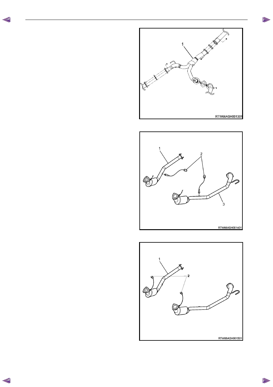
Remove the centre exhaust pipe (1), refer to 6F
Exhaust System - V6 - V6.
Figure 6A1 – 327
29
Disconnect the two post-catalytic converter oxygen
sensor wiring harness connectors, 1 each bank.
Figure 6A1 – 328
30
Disconnect the two pre-catalytic converter oxygen
sensor wiring harness connectors, 1 each bank.
31
Remove the front exhaust flange nuts, three each
bank.
32
Remove the front left-hand exhaust pipe from the
rubber mount.
33
Remove the front exhaust pipes from the vehicle, for
further information, refer to 6F Exhaust System - V6.
Figure 6A1 – 329
34
Remove the transfer case from the vehicle (4WD Only), refer to 7D Transfer Case and Adaptor Housing.
Engine Mechanical – V6
Page 6A1–190
35
Disconnect the harness connector from the transmission, refer to 7B1 Manual Transmission – V6 or 7C1, 2, 3 or 4
for automatic transmission.
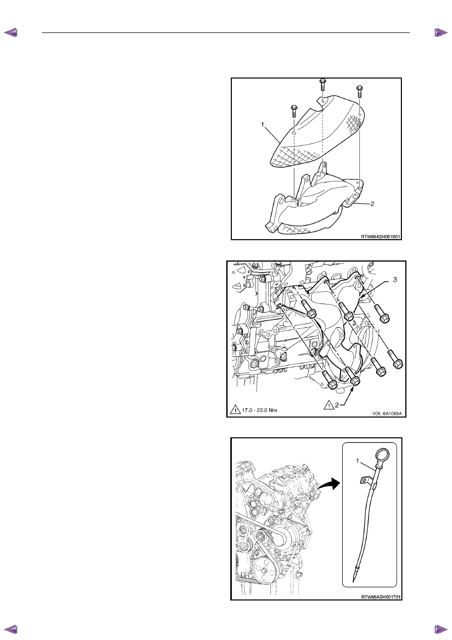
36
Remove the left-hand side exhaust manifold upper
heat shield (1), (Automatic transmission only).
Figure 6A1 – 330
37
Progressively loosen the seven exhaust manifold
attaching bolts (2), working from the outside to the
centre and then remove the bolts.
38
Manoeuvre the exhaust manifold (3), away from the
cylinder head.
39
Remove and discard the exhaust manifold to cylinder
head gasket.
Figure 6A1 – 331
40
Remove the engine oil level indicator assembly (1),
(automatic transmission only).
41
Remove the left-hand side exhaust manifold,
(automatic transmission only).

Engine Mechanical – V6
Page 6A1–191
Figure 6A1 – 332
Figure 6A1 – 333
Figure 6A1 – 334
42
Fit the engine lifting brackets (1), (EN–46114) and attach the engine hoist, raise the engine to take the weight off
the engine mounts.
Engine Lift Bracket Attaching Bolt
torque specification
. . . . . . . . . . . . . . . .58.0 – 72.0.0 Nm
43
Remove the left-hand side knock sensor (1).
Figure 6A1 – 335
N O T E
Removal or the starter motor is only required for
vehicles with an Automatic Transmission.
Engine Mechanical – V6
Page 6A1–192
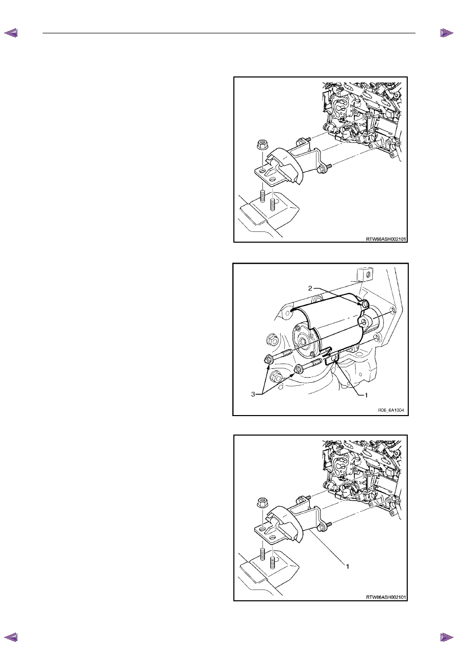
44
Remove the left-hand side engine mount (1),
(automatic transmission only).
Figure 6A1 – 336
45
Unclip the oil level sensor harness from the heat
shield (1).
a
Remove the heat shield retaining screw (2).
b
Remove the lower starter motor attaching bolt (3).
c
Remove the heat shield.
d
Remove the upper starter motor retaining bolt (3).
46
Remove the starter motor from the engine block and
lower the starter motor as far as possible to gain
access to the wiring harness connections.
47
Remove the starter motor, (automatic transmission
only).
Figure 6A1 – 337
48
Reinstall the left-hand side engine mount (1),
(automatic transmission only).
49
Remove the transmission assembly, refer to 7C1
Automatic – 4L60E – General Information.
Нет комментариевНе стесняйтесь поделиться с нами вашим ценным мнением.
Текст