Isuzu KB P190. Manual — part 830

Engine Management – V6 – Diagnostics
Page 6C1-2–42
6.3
Fuel Injector Balance Test
To avoid irregular fuel pressure readings, do
not perform this procedure if the engine
coolant temperature is greater than 94
°°°° C.
Fuel Injector Balance Test – With Tech 2
1
Check the engine coolant temperature is less than 94
°C.
2
Perform the fuel injector coil test and replace any fuel injectors that are not functioning correctly before proceeding.
Refer to 6.2
Fuel Injector Coil Test.
3
Perform the fuel system pressure check and ensure the fuel system is functioning correctly before proceeding with
the fuel injector balance test. Refer to 6C Fuel System – V6.
4
While the fuel pressure gauge is still connected to the fuel pressure test point, pressurise the fuel system. Refer to
6C Fuel System – V6.
5
When the fuel pressure reading stabilises, record the fuel pressure reading indicated by the fuel pressure gauge.
N O T E
The fuel pressure reading taken in Step 5 is
known as the first pressure reading.
6
Connect Tech 2 to the data link connector (DLC) and turn the ignition on.
7
On Tech 2 select Engine / V6 Engine / Actuator Test / Fuel Injector Balance.
8
Follow the Tech 2 prompts, recording the fuel pressure gauge reading for each injector.
N O T E
The fuel pressure readings taken in Step 8 are
known as the second pressure reading
9
Perform the Fuel Injector Pressure Drop Calculation in this Section.
Fuel Injector Balance Test – Without Tech 2
1
Check the engine coolant temperature is less than 94
°C.
2
Perform the fuel injector coil test and replace any fuel injectors that are not functioning correctly before proceeding.
Refer to 6.2 Fuel Injector Coil Test.
3
Perform the fuel system pressure check and ensure the fuel system is functioning correctly before proceeding with
the fuel injector balance test. Refer to 6C Fuel System – V6.
4
While the fuel pressure gauge is still connected to the fuel pressure test point, pressurise the fuel system. Refer to
6C Fuel System – V6.
5
When the fuel pressure reading stabilises, record the fuel pressure reading indicated by the fuel pressure gauge.
N O T E
The fuel pressure reading taken in Step 5 is
known as the first pressure reading.
Engine Management – V6 – Diagnostics
Page 6C1-2–43
6
Remove the upper intake manifold assembly, refer to 6A1 Engine Mechanical – V6.
N O T E
After removing the upper intake manifold, plug
the lower manifold opening to prevent dirt and
other contaminants from entering.
7
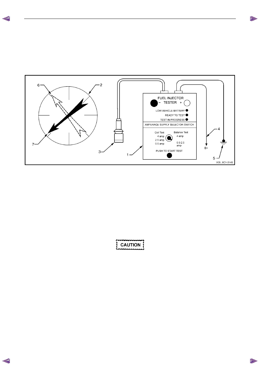
Connect Tool No. J 39021 Fuel Injector Tester (1), and Tool No. J 44602 (3) to the fuel injector connector. Refer to
Figure 6C1-2 – 14.
Figure 6C1-2 – 14
Legend
1
Fuel Injector Tester – Special Tool J39021
2
Fuel Pressure Gauge – Special Tool SD28018
3
Fuel Injector Harness Adapter – Special Tool J44602
4
To Battery Positive Terminal
5 Battery
Earth
6
First Pressure Reading
7
Second Pressure Reading
8
Connect the fuel injector tester battery positive lead (4) and battery negative lead (5) to the battery, refer to Figure
6C1-2 – 14.
9
Set the amperage supply selector of the fuel injector tester to the Balance Test 0.5 – 2.5 A position.
As the fuel pressure tends to increase after
the fuel injector stops fuel delivery, record the
fuel pressure value immediately after the fuel
injector stops fuel delivery. Do not record the
higher fuel pressure value.
10
Press the Push to Start Test Button on the fuel injector tester to activate the fuel injector.
11
Record the fuel pressure reading indicated by the fuel pressure gauge.
N O T E
The fuel pressure readings taken in Step 10 is
known as the second pressure reading
12
Repeat the balance test pressure reading for each fuel injector.
13
Perform the Fuel Injector Pressure Drop Calculation in this Section.
Engine Management – V6 – Diagnostics
Page 6C1-2–44
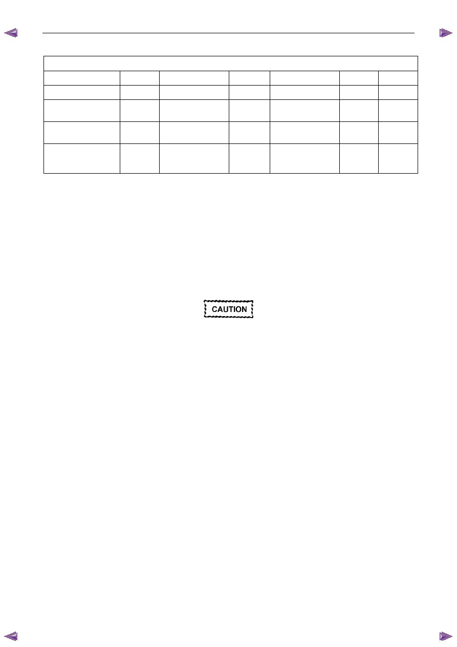
Fuel Injector Pressure Drop Calculation
Fuel Injector Balance Test Example – Typical Values Shown
Cylinder 1
2
3
4
5
6
1st Pressure Reading
360 kPa
360 kPa
360 kPa
360 kPa
360 kPa
360 kPa
2nd Pressure
Reading
155 kPa
131 kPa
155 kPa
200 kPa
146 kPa
150 kPa
Amount of Pressure
Drop
205 kPa
229 kPa
205 kPa
160 kPa
214 kPa
210 kPa
Average Range
194 - 214 kPa
Injector
OK
Replace fuel
injector – too much
pressure drop
Injector
OK
Replace fuel
injector – too little
pressure drop
Injector
OK
Injector
OK
Figure 6C1-2 – 15
1
Subtract the second pressure reading from the first pressure reading to calculate the pressure drop value. Refer to
the table in Figure 6C1-2 – 15, typical results.
2
Calculate the pressure drop value for each fuel injector.
3
Add all the individual pressure drop values of each fuel injector to calculate the total pressure drop.
4
Divide the total pressure drop by the number of fuel injectors to calculate the average pressure drop.
Fuel Injector Pressure Drop Analysis
1
A fuel injector is faulty if its pressure drop value deviates from the average pressure drop by more than 10 kPa.
Do not repeat any portion of the test before
running the engine to prevent the engine from
flooding.
2
Re-test any fuel injector that does not meet the specification.
3
Replace all faulty fuel injectors, refer to 2.13 Fuel Rail Assembly, in 6C1-3 Engine Management – V6 – Service
Operations.
6.4
Fuel Injector Leak Down Test
1
Turn the ignition switch OFF.
N O T E
After removing the upper intake manifold, plug
the lower manifold opening to prevent dirt and
other contaminants from entering.
2
Remove the upper intake manifold assembly, refer to 6A1 Engine Mechanical – V6.
Engine Management – V6 – Diagnostics
Page 6C1-2–45
Clean around the area where the fuel
injectors enter the lower intake manifold.
3
Remove the bolt (1), three places, attaching the fuel
rail to the lower intake manifold.
Care must be taken when removing the fuel
rail and injector assembly to prevent damage
to the injector spray tips and injector harness
connector terminals.
Support the fuel rail and injector assembly
after removal.
4
Lift up and support the fuel rail and injector assembly.
N O T E
Do not disconnect the fuel feed hose from the
fuel rail.
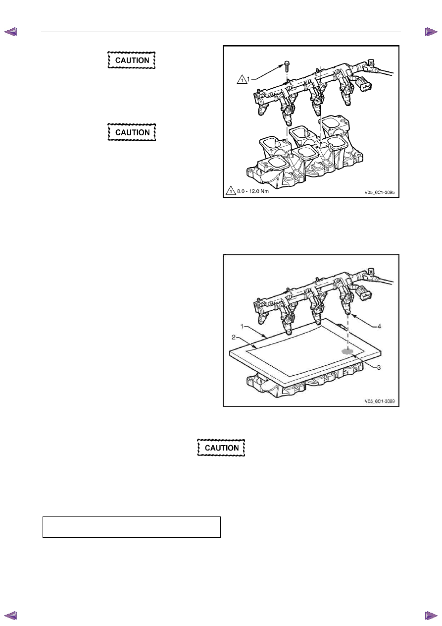
Figure 6C1-2 – 16
5
Place a board (1) with a sheet of clean paper (2),
preferably white, onto the lower intake manifold.
6
Using Tech 2, enable the fuel pump to pressurise the
fuel system.
7
Whilst the fuel system is pressurised, check the
following:
•
Signs of fuel stains on the paper (3).
•
Signs of weeping at the fuel injector spray
tips (4).
8
If any of the above conditions are present, replace the
leaking fuel injector/s, refer to 2.13 Fuel Rail
Assembly, in 6C1-3 Engine Management – V6 –
Service Operations.
9
Carefully reinstall the fuel rail and injector assembly.
Figure 6C1-2 – 17
Ensure the fuel injectors are correctly seated
in the lower intake manifold, and the fuel rail
attaching brackets are correctly located prior
to tightening the attaching bolts.
10
Tighten the fuel rail bolts to the correct torque specification.
Fuel rail attaching bolt
torque specification . . . . . . . . ..8.0 – 12.0 Nm
11
Reinstall the upper intake manifold assembly, refer to 6A1 Engine Mechanical – V6.
12
Inspect the fuel rail and quick connect fitting for leaks, refer to 6C Fuel System – V6.
13
Road test the vehicle and check for correct operation.
Нет комментариевНе стесняйтесь поделиться с нами вашим ценным мнением.
Текст