Isuzu KB P190. Manual — part 882
Engine Management – V6 – Service Operations
Page 6C1-3–4
1 General
Information
1.1 General
Description
This Section describes the correct service procedures to repair and test components of the V6 engine management
system. Emphasis is placed on the proper procedures and repair of components related to this specific system.
For component description, operation and location, refer to 6C1-1 Engine Management – V6 – General Information.
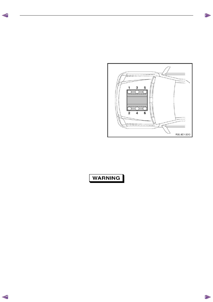
Engine cylinder identification follows the international
standard OBD II. This standard calls for the engine cylinder
bank number one to be identified by the location of cylinder
number one. Therefore the numbering for the V6 engine is:
•
1, 3, 5 – Right-hand side (Bank 1).
•
2, 4, 6 – Left-hand side (Bank 2).
The engine firing order is 1, 2, 3, 4, 5, 6.
Figure 6C1-3 – 1
1.2
Service Precautions and Requirements
Service Precautions
The following safety and precautionary
directions must be followed when servicing
the engine management system otherwise
personal injury and / or improper system
operation may occur:
•
If working on a vehicle which has been subjected to an under bonnet thermal incident (fire), wear appropriate
protective clothing to prevent personal injury. Components that contain fluoro-elastomer may produce a corrosive
bi-product when subjected to extreme heat.
•
Disconnection of the battery affects certain vehicle electronic systems. Refer to the battery disconnection
procedure in 6D1-3 Battery – V6 before disconnecting the battery.
•
Disconnect the battery negative lead when performing the following procedures:
•
disconnecting the engine control module (ECM) connectors, or
•
charging the battery.
•
Disconnect the battery negative lead and the ECM connectors before attempting any electric welding on the vehicle.
•
Do not start the engine if the battery terminal is not properly secured to the battery.
•
Do not disconnect or reconnect the following while the ignition is switched on or when the engine is running:
•
any engine management system component wiring connector, or
•
battery terminal leads.
Engine Management – V6 – Service Operations
Page 6C1-3–5
•
Ensure the correct procedure for disconnecting and connecting engine management system wiring connectors is
always followed.
•
Ensure that all wiring connectors are fitted correctly.
•
The engine management system wiring connectors are designed to fit only one way; there are indexing tabs and
slots on both halves of the connector. Forcing the connector into place is not necessary if it is being installed with
the correct orientation. Failure to take care to match the indexing tabs and slots correctly can cause damage to the
connector, the module, or other vehicle components or systems.
•
Never touch the connector pins of any electronic component, such as an ECM, as electrostatic discharge (ESD)
damage may result.
•
When steam or pressure cleaning engines, do not direct the cleaning nozzle at engine management system
components.
•
Never subject the ECM to temperatures less than -40
° C and greater than 125° C.
•
Prior to disconnection or removal of any components associated with the fuel system, clean the area around any
connection points to avoid possible contamination of the fuel system.
•
A depressurised fuel system contains fuel in the fuel system and fuel lines that can be spilled during service
operations. To reduce the chance of personal injury, cover the fittings with a shop towel to absorb any fuel spillage
prior to performing the service operation. Once the service operation has been completed, place the towel in an
approved container for disposal.
•
To avoid accidental fuel discharge, it is advisable to disconnect the battery and remove the fuel pump relay if the
fuel line between the fuel pump and the fuel rail is to be disconnected / open for an indefinite period.
•
Always tighten fasteners to the correct tightening torque, and where indicated in the service procedure, follow the
correct tightening sequence, precautions and recommendations to prevent premature failure of the fastener or
component.
•
After removing components, such as the upper or lower intake manifold, front engine pipe, heated oxygen sensor,
etc. always plug any openings to prevent dirt and other contaminants from entering.
•
Do not use silicone based assembly lubricants as damage to the heated oxygen sensors may result.
Use of incorrect electrical test equipment
when performing engine management service
procedures could result in incorrect results or
component damage.
•
Use only the test equipment specified in the diagnostic tables. Use of other test equipment may either give
incorrect results or damage serviceable components, refer to, 6C1-2 Engine Management – V6 – Diagnostics.
•
After completing the required service operations, road test the vehicle to ensure correct engine management
system operation.
Service Requirements
Basic Knowledge Required
A lack of basic understanding of electronics,
electrical wiring circuits and use of electrical
circuit testing tools when performing certain
service procedures could result in incorrect
results or damage to components.
In addition, a general understanding of the engine management system and its component operation is essential to
prevent misdiagnosis and component damage.

Engine Management – V6 – Service Operations
Page 6C1-3–6
Basic Diagnostic Tools Required
Use of incorrect electrical circuit diagnostic
tools when performing certain service
procedures could result in incorrect
diagnostic results or damage to components.
The following electrical circuit testing tools are required to perform the diagnostic procedures detailed in this Section:
•
Test lamp, refer to 8A Electrical – Body and Chassis for further information.
•
Digital multimeter with 10 M
Ω ohms impedance, refer to 8A Electrical – Body and Chassis for further information.
•
Connector test adapter kit Tool No. J35616-A.
1.3
Service Operations Not Covered In This
Section
There are situations where components and/or procedures related to the powertrain management system are covered in
other Sections of the service documentation. To aid technicians in locating the necessary service procedures for these
components and/or procedures, refer to the stated references.
Air-conditioning System
For A/C pressure switch replacement procedure, refer to 2A Heater and Air-conditioning.
Electrical Components
For the following electrical system component replacement procedures, refer to the appropriate Sections as follows:
•
Extended brake pedal travel switch and stop lamp switch service operations, refer to 5C Brakes.
•
Fuse and relay locations, refer to 8A Electrical-Body and Chassis.
•
Cruise control switch assembly service operations, refer to 8C Cruise Control – HFV6.
•
Powertrain interface module PIM removal and installation procedure, refer to 6E1 Powertrain Interface Module – V6.
•
Neutral start and back-up lamp switch, refer to 7C4 Automatic Transmission – 4L60E – On-vehicle Servicing.
•
Vehicle speed sensor service operations, refer to:
−
7C4 Automatic Transmission – 4L60E – On-vehicle Servicing
−
7B1 Manual Transmission – V6
Fuel System
For the following fuel system component replacement procedures, refer to 6C Fuel System – V6.
•
Fuel system cleaning,
•
Fuel system leak and pressure test,
•
Fuel feed hose to fuel rail replacement,
•
Fuel line quick connect fittings,
•
Evaporative emission control canister,
•
Fuel filter,
•
Fuel hose / pipes layout,
•
Fuel pump motor assembly and fuel pressure regulator assembly,
•
Fuel sender assembly service operations.
Engine Management – V6 – Service Operations
Page 6C1-3–7
Transmission – Automatic
For automatic transmission sensors and components, refer to 7C4 Automatic Transmission – 4L60E – On-vehicle
Servicing.
Transmission – Manual
For manual transmission sensors and other components, refer to 7B1 Manual Transmission – V6.
1.4
Warning Caution and Notes
This Section contains various WARNINGS, CAUTIONS and NOTE statements that you must observe carefully to reduce
the risk of death or injury during service, repair procedures or vehicle operation. Incorrect service or repair procedures
may damage the vehicle or cause operational faults. WARNINGS, CAUTION and NOTE statements are not exhaustive.
GM Holden LTD can not possibly warn of all the potentially hazardous consequences of failure to follow these
instructions.
Definition of WARNING, CAUTION and NOTE Statements
Diagnosis and repair procedures in this Section contain both general and specific WARNING, CAUTION and NOTE
statements. GM Holden LTD is dedicated to the presentation of service information that helps the technician to diagnose
and repair the systems necessary for proper operation of the vehicle. Certain procedures may present a hazard to the
technician if they are not followed in the recommended manner. WARNING, CAUTION and NOTE statements are
designed to help prevent these hazards from occurring, but not all hazards can be foreseen.
WARNING defined
A WARNING statement immediately precedes an operating procedure or maintenance practice which, if not correctly
followed, could result in death or injury. A WARNING statement alerts you to take necessary action or not to take a
prohibited action. If a WARNING statement is ignored, the following consequences may occur:
•
Death or injury to the technician or other personnel working on the vehicle,
•
Death or injury to other people in or near the workplace area, and / or
•
Death or injury to the driver / or passenger(s) of the vehicle or other people, if the vehicle has been improperly
repaired.
CAUTION defined
A CAUTION statement immediately precedes an operating procedure or maintenance practice which, if not correctly
followed, could result in damage to or destruction of equipment, or corruption of data. If a CAUTION statement is ignored,
the following consequences may occur:
•
Damage to the vehicle,
•
Unnecessary vehicle repairs or component replacement,
•
Faulty operation or performance of any system or component being repaired,
•
Damage to any system or components which depend on the proper operation of the system or component being
repaired,
•
Faulty operation or performance of any systems or components which depend on the proper operation or
performance of the system or component under repair,
•
Damage to fasteners, basic tools or special tools and / or
•
Leakage of coolant, lubricant or other vital fluids.
NOTE defined
A NOTE statement immediately precedes or follows an operating procedure, maintenance practice or condition that
requires highlighting. A NOTE statement also emphasises necessary characteristics of a diagnostic or repair procedure.
A NOTE statement is designed to:
•
Clarify a procedure,
•
Present additional information for accomplishing a procedure,
Нет комментариевНе стесняйтесь поделиться с нами вашим ценным мнением.
Текст