Isuzu KB P190. Manual — part 883
Engine Management – V6 – Service Operations
Page 6C1-3–8
•
Give insight into the reasons for performing a procedure in the recommended manner, and / or
•
Present information that gives the technician the benefit of past experience in accomplishing a procedure with
greater ease.
Engine Management – V6 – Service Operations
Page 6C1-3–9
2
General Service Operations
2.1
Accelerator Pedal Position Sensor
Remove
1
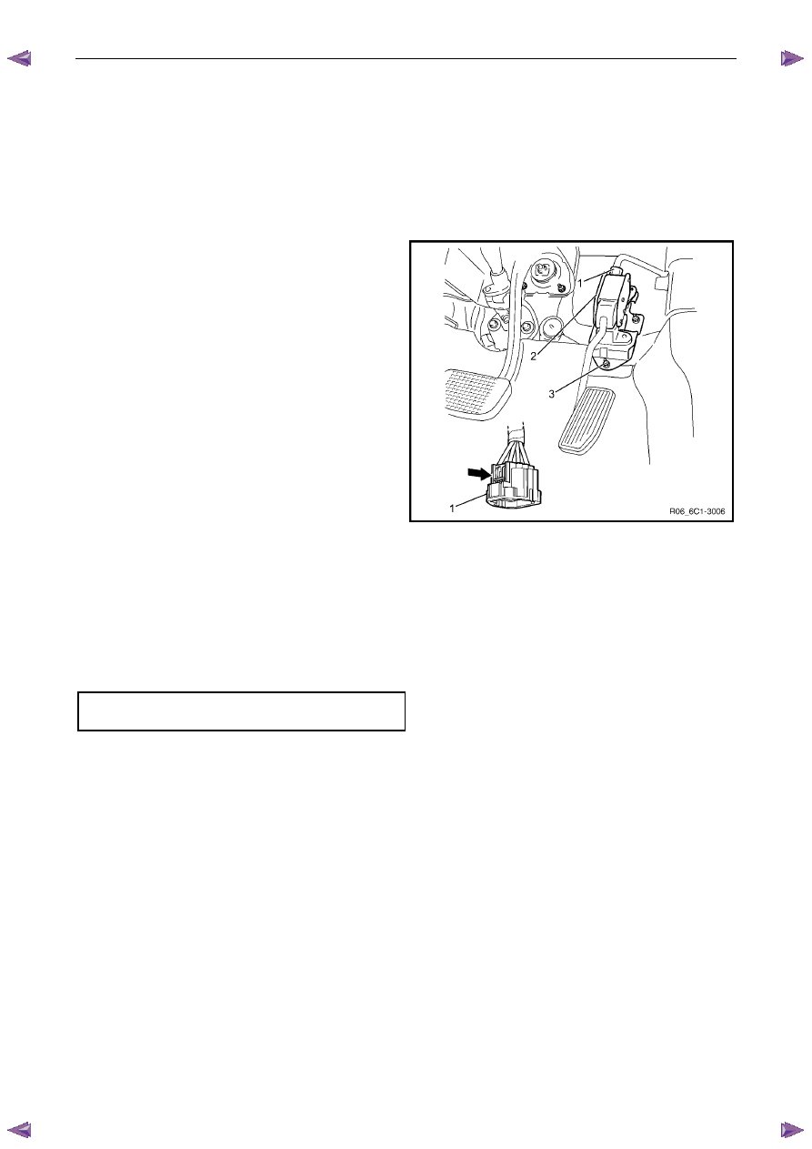
Turn the ignition switch off.
2
Disconnect the wiring harness connector (1) from the
accelerator pedal position (APP) sensor (2) by
depressing the latch in the direction of the arrow.
N O T E
If difficulty is experienced in disconnecting the
harness connector from the APP sensor, remove
the sensor and mounting bracket assembly and
then disconnect the harness connector.
3
Remove the nut (3), two places, attaching the APP
sensor and bracket assembly to the dash panel.
Figure 6C1-3 – 2
Reinstall
Reinstallation of the accelerator pedal position (APP) sensor is the reverse of the removal procedure, noting the
following:
1
Reinstall the bolts attaching the APP sensor to the support bracket and tighten to the correct torque specification.
Accelerator pedal position sensor attaching bolt
torque specification . . . . . . . . ...8.5 – 11.5 Nm
2
Road test the vehicle and check for correct operation.
2.2
Air Cleaner Assembly
Air Cleaner Upper Housing
Remove
1
Turn the ignition switch off.
2
Remove the mass air flow (MAF) sensor, refer to 2.20
Mass Air Flow Sensor.
Engine Management – V6 – Service Operations
Page 6C1-3–10
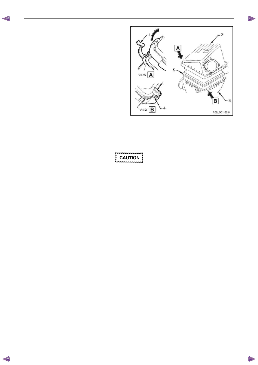
3
Release the retaining clip (1), two places, attaching
the air cleaner upper housing (2) to the air cleaner
lower housing (3).
4
Rotate the upper housing in the direction of the arrow
and withdraw the housing while disengaging the two
outer retaining lugs (4).
5
If necessary, remove the air cleaner element (5).
Figure 6C1-3 – 3
Reinstall
Reinstallation of the air cleaner upper housing is the reverse of the removal procedure, noting the following:
Ensure the air cleaner sealing rubber is
correctly located in the air cleaner lower
housing. Failure to do this may result in
engine damage due to unfiltered air entering
the engine intake system.
1
Reinstall the air cleaner element.
2
Reinstall the air cleaner upper housing aligning the outer retaining lugs.
3
Reinstall the air cleaner upper housing ensuring the upper housing retaining clips are correctly located.
4
Road test the vehicle and check for correct operation, taking particular note that no air leaks are evident.
Air Cleaner Lower Housing Assembly
Remove
1
Turn the ignition switch off.
2
Remove the air cleaner upper housing as described previously.
Engine Management – V6 – Service Operations
Page 6C1-3–11
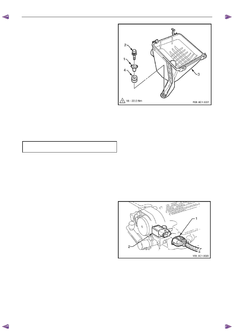
3
Using a suitable lever, gently lever the locking tangs
(1) of the lower housing insulator sleeve back to clear
the lower housing retaining bolt (2). Repeat this
process for each of the remaining two sleeves.
4
Remove the three bolts retaining the lower housing (3)
to the fender inner panel and remove the housing.
5
If required, remove the insulator sleeve and air cleaner
lower housing insulator (4).
Figure 6C1-3 – 4
Reinstall
1
Reinstall the air cleaner lower housing attaching bolt and tighten to the correct torque specification.
Air cleaner lower housing attaching
bolt torque specification . . . . . . ..18.0 – 22.0 Nm
2
Using a suitable hammer and pin punch, position the locking tang against the bolt head.
3
Road test the vehicle and check for correct operation.
2.3
Barometric Pressure Sensor
Remove
1
Turn the ignition switch off.
2
Disconnect the wiring harness connector (1) from the
barometric pressure (BARO) sensor (2).
Figure 6C1-3 – 5
Нет комментариевНе стесняйтесь поделиться с нами вашим ценным мнением.
Текст