Isuzu KB P190. Manual — part 581

6E–154
ENGINE DRIVEABILITY AND EMISSIONS
9
1. Using the Tech 2, ignition “On” and engine “On”.
2. Monitor the “Manifold Absolute Pressure” in the
data display.
Does the Tech 2 indicate correct “Manifold Absolute
Pressure” in accordance with engine speed or
acceleration?
—
Go to Step 11
Go to Step 10
10
Remove the MAP sensor and check for the following
conditions.
• Objects blocking the air cleaner.
• Objects blocking the MAP sensor.
• Objects blocking the throttle valve.
• Vacuum leaking at intake duct.
• Vacuum leaking at throttle body.
If a problem is found, repair as necessary.
Was the problem found?
—
Verify repair
Go to Step 11
11
1. Using the Tech 2, ignition “On” and engine “On”.
2. Select the “Miscellaneous Test” and perform the
“IAC Control” in the “IAC System”.
3. Operate the Tech 2 in accordance with procedure.
Was the engine speed changed, when the IAC valve
is operating step by step?
—
Go to Step 13
Go to Step 12
12
Check for the following conditions.
• Objects blocking the IAC valve.
• Objects blocking the throttle valve.
• Vacuum leaking at throttle body.
If a problem is found, repair as necessary.
Was the problem found?
—
Verify repair
Go to Step 13
13
Check for injector for the affected bank.
Refer to “Injector Coil Test & Injector Balance Test
Procedure” 6E-98 page.
Was the injector operation correct?
—
Go to Step 14
Refer to Injector
Coil Test &
Injector
Balance Test
Procedure
14
Check for fuel pressure.
Refer to “Fuel System Diagnosis” 6E-108 page.
Was the fuel pressure correct?
—
Go to Step 15
Refer to Fuel
System
Diagnosis
15
Replace the O
2
sensor.
Was the problem solved?
—
Verify repair
Go to Step 16
16
Is the ECM programmed with the latest software
release?
If not, download the latest software to the ECM using
the “SPS (Service Programming System)”.
Was the problem solved?
—
Verify repair
Go to Step 17
17
Replace the ECM.
Is the action complete?
IMPORTANT: The replacement ECM must be
programmed. Refer to section of the Service
Programming System (SPS) in this manual.
Following ECM programming, the immobilizer system
(if equipped) must be linked to the ECM. Refer to
section 11 “Immobilizer System-ECM replacement” for
the ECM/Immobilizer linking procedure.
—
Verify repair
—
Step
Action
Value(s)
Yes
No
ENGINE DRIVEABILITY AND EMISSIONS
6E–155
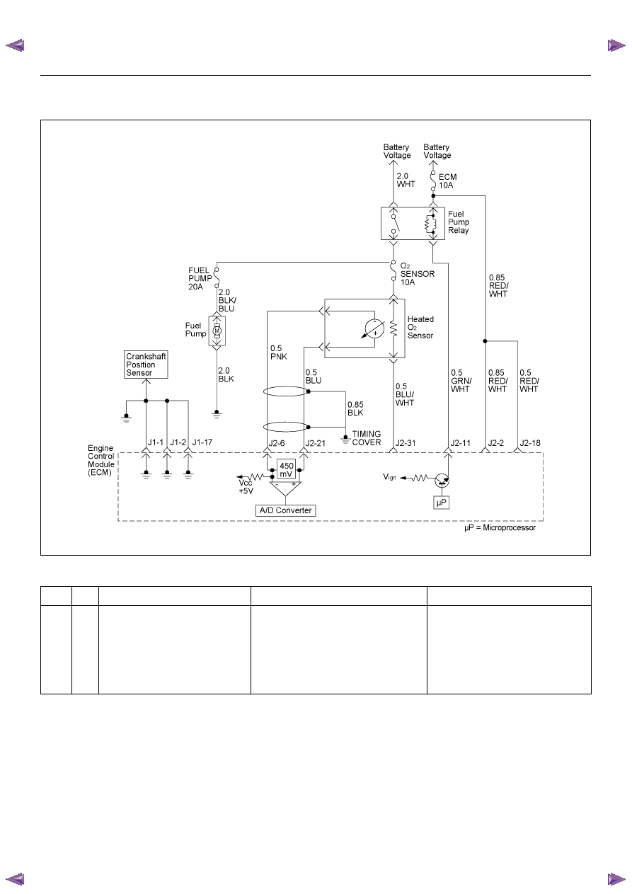
DIAGNOSTIC TROUBLE CODE (DTC) P0132 O
2
SENSOR CIRCUIT HIGH
VOLTAGE (BANK 1 SENSOR 1)
Condition for setting the DTC and action taken when the DTC sets
Circuit Description
The engine control module (ECM) supplies a bias
voltage of about 450 mV between the heated oxygen
sensor (HO2S) signal and low circuits. The oxygen
sensor varies the voltage within a range of about 1000
mV when the exhaust is rich, down through about 10
mV when exhaust is lean. The ECM constantly monitors
the HO2S signal during “Closed Loop” operation and
compensates for a rich or lean condition by decreasing
or increasing injector pulse width as necessary. If the
Bank 1 HO2S 1 voltage remains excessively high for an
extended period of time, Diagnostic Trouble Code
P0132 will be set.
Diagnostic Aids
Check the following items:
• Fuel pressure - The system will go rich if pressure is
too high. The ECM can compensate for some
increase. However, if fuel pressure is too high, a
Diagnostic Trouble Code P0132 may be set. Refer to
Code
Type
DTC Name
DTC Setting Condition
Fail-Safe (Back Up)
P0132
A
O
2
Sensor Circuit High Voltage (Bank 1
Sensor 1)
1. No DTC relating to MAP sensor, TPS,
EVAP purge, ECT sensor, CKP sensor,
VSS, injector control circuit and ignition
control circuit.
2. Engine coolant temperature is more than
60 deg. C.
3. O
2
sensor bank 1 output voltage is more
than 952mV in “Closed Loop” condition.
“Open Loop” fuel control.
6E–156
ENGINE DRIVEABILITY AND EMISSIONS
Fuel System Diagnosis.
• Perform “Injector Balance Test” - Refer to Fuel
System Diagnosis.
• Check the EVAP canister for fuel saturation - If full of
fuel, check canister control and hoses. Refer to
Evaporative (EVAP) Emission Control System.
• Check for a leak in the fuel pressure regulator
diaphragm by checking the vacuum line to the
regulator for the presence of fuel.
• An intermittent TPS output will cause the system to
go rich due to a false indication of the engine
accelerating.
• Silicon contamination of the HO2S can also cause a
high HO2S voltage to be indicated. This condition is
indicated by a powdery white deposit on the portion
of the HO2S exposed to the exhaust stream. If
contamination is noticed, replace the affected HO2S.
Diagnostic Trouble Code (DTC) P0132
O
2
Sensor Circuit High Voltage (Bank 1 Sensor 1)
Step
Action
Value(S)
Yes
No
1
Was the “On-Board Diagnostic (OBD) System Check”
performed?
—
Go to Step 2
Go to On Board
Diagnostic
(OBD) System
Check
2
1. Connect the Tech 2.
2. Review and record the failure information.
3. Select “F0: Read DTC Infor By Priority” in “F0:
Diagnostic Trouble Code”.
Is the DTC P0132 stored as “Present Failure”?
—
Go to Step 3
Refer to
Diagnostic Aids
and Go to Step
3
3
1. Using the Tech2, ignition “On” and engine “Off”.
2. Select “Clear DTC Information” with the Tech2 and
clear the DTC information.
3. Operate the vehicle and monitor the “F5: Failed
This Ignition” in “F2: DTC Information”.
Was the DTC P0132 stored in this ignition cycle?
—
Go to Step 4
Refer to
Diagnostic Aids
and Go to Step
4
4
Check for poor/faulty connection at the O
2
sensor or
ECM connector. If a poor/faulty connection is found,
repair as necessary.
Was the problem found?
—
Verify repair
Go to Step 5
5
Using the DVM and check the O
2
sensor circuit.
1. Ignition “On”, engine “Off”.
2. Disconnect the the O
2
sensor connector.
3. Check the circuit for short to power supply circuit.
Was the DVM indicated specified value?
Approximatly
450mV
Go to Step 7
Go to Step 6
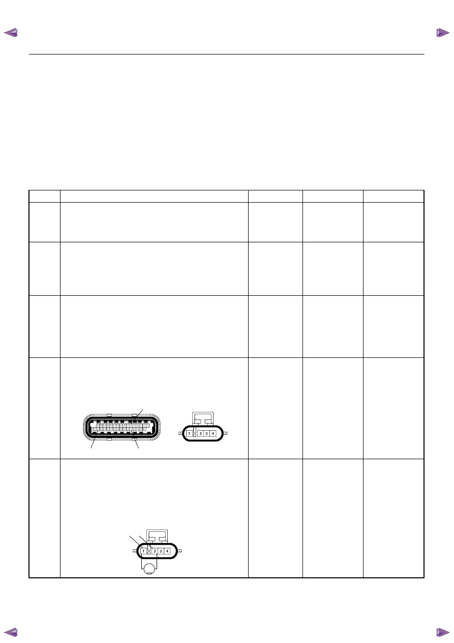
C56(J2)
E77
31
21
6
V
2
1
E77

ENGINE DRIVEABILITY AND EMISSIONS
6E–157
6
Using the DVM and check the O
2
sensor circuit.
1. Ignition “On”, engine “Off”.
2. Disconnect the O
2
sensor connector.
3. Check the circuit for short to power supply circuit.
Was the DVM indicated specifed value?
Less than 1V
Go to Step 15
Repair faulty
harness and
verify repair
7
Using the DVM and check the O
2
sensor circuit.
1. Ignition “Off”, engine “Off”.
2. Disconnect the the O
2
sensor connector.
3. Check the circuit for short to heater power supply
circuit.
Was the DVM indicated specified value?
No continuity
Go to Step 9
Go to Step 8
8
Repair the short to heater power supply circuit.
Was the problem found?
—
Verify repair
Go to Step 15
9
1. Using the Tech 2, ignition “On” and engine “On”.
2. Monitor the “Manifold Absolute Pressure” in the
data display.
Does the Tech 2 indicate correct “Manifold Absolute
Pressure” in accordance with engine speed or
acceleration?
—
Go to Step 11
Go to Step 10
10
Remove the MAP sensor and check for the following
conditions.
• Objects blocking the air cleaner.
• Objects blocking the MAP sensor.
• Objects blocking the throttle valve.
• Vacuum leaking at intake duct.
• Vacuum leaking at throttle body.
If a problem is found, repair as necessary.
Was the problem found?
—
Verify repair
Go to Step 11
11
1. Using the Tech 2, ignition “On” and engine “On”.
2. Select the “Miscellaneous Test” and perform the
“IAC Control” in the “IAC System”.
3. Operate the Tech 2 in accordance with procedure.
Was the engine speed changed, when the IAC valve
is operating step by step?
—
Go to Step 13
Go to Step 12
Step
Action
Value(S)
Yes
No
1 2
V
V
E77
1
2
4
1
2
3
4
O
2
Sensor
Нет комментариевНе стесняйтесь поделиться с нами вашим ценным мнением.
Текст