Isuzu KB P190. Manual — part 582

6E–158
ENGINE DRIVEABILITY AND EMISSIONS
12
Check for the following conditions.
• Objects blocking the IAC valve.
• Objects blocking the throttle valve.
• Vacuum leaking at throttle body.
If a problem is found, repair as necessary.
Was the problem found?
—
Verify repair
Go to Step 13
13
Check for injector for the affected bank.
Refer to “Injector Coil Test & Injector Balance Test
Procedure” 6E-98 page.
Was the injector operation correct?
—
Go to Step 14
Refer to Injector
Coil Test &
Injector
Balance Test
Procedure
14
Check for fuel pressure.
Refer to “Fuel System Diagnosis” 6E-108 page.
Was the fuel pressure correct?
—
Go to Step 15
Refer to Fuel
System
Diagnosis
15
Replace the O
2
sensor.
Was the problem solved?
—
Verify repair
Go to Step 16
16
Is the ECM programmed with the latest software
release?
If not, download the latest software to the ECM using
the “SPS (Service Programming System)”.
Was the problem solved?
—
Verify repair
Go to Step 17
17
Replace the ECM.
Is the action complete?
IMPORTANT: The replacement ECM must be
programmed. Refer to section of the Service
Programming System (SPS) in this manual.
Following ECM programming, the immobilizer system
(if equipped) must be linked to the ECM. Refer to
section 11 “Immobilizer System-ECM replacement” for
the ECM/Immobilizer linking procedure.
—
Verify repair
—
Step
Action
Value(S)
Yes
No

ENGINE DRIVEABILITY AND EMISSIONS
6E–159
DIAGNOSTIC TROUBLE CODE (DTC) P0134 O
2
SENSOR NO ACTIVITY
DEFECTED (BANK 1 SENSOR 1)
Condition for setting the DTC and action taken when the DTC sets
Circuit Description
The engine control module (ECM) supplies a bias
voltage of about 450 mV between the heated oxygen
sensor (HO2S) high and low circuits. The oxygen
sensor varies the voltage within a range of about 1000
mV when the exhaust is rich, down through about 10
mV when exhaust is lean. The ECM constantly monitors
the HO2S signal during “Closed Loop” operation and
compensates for a rich or lean condition by decreasing
or increasing injector pulse width as necessary. If the
Bank 1 HO2S 1 voltage remains at or near the 450 mV
bias for an extended period of time, Diagnostic Trouble
Code P0134 will be set, indicating an open sensor
signal or sensor low circuit.
Code
Type
DTC Name
DTC Setting Condition
Fail-Safe (Back Up)
P0134
A
O
2
Sensor Circuit No Activity Detected
(Bank 1 Sensor 1)
1. No DTC relating to MAP sensor, TPS,
EVAP purge, ECT sensor, CKP sensor,
VSS, injector control circuit and ignition
control circuit.
2. Engine coolant temperature is more than
60 deg.C.
3. Engine run time is longer than 40 seconds.
4. Mass air flow is more than 7g/s.
5. O
2
sensor bank 1 output voltage is
between 300mV and 600mV.
“Open Loop” fuel control.
6E–160
ENGINE DRIVEABILITY AND EMISSIONS
Diagnostic Aids
Check for the following conditions:
• Poor connection or damaged harness - Inspect the
harness connectors for backed-out terminals,
improper mating, broken locks, improperly formed or
damaged terminals, poor terminal-to-wire connection,
and damaged harness.
Diagnostic Trouble Code (DTC) P0134
O
2
Sensor Circuit No Activity Detected (Bank 1 Sensor 1)
Step
Action
Value(s)
Yes
No
1
Was the “On-Board Diagnostic (OBD) System Check”
performed?
—
Go to Step 2
Go to On Board
Diagnostic
(OBD) System
Check
2
1. Connect the Tech 2.
2. Review and record the failure information.
3. Select “F0: Read DTC Infor By Priority” in “F0:
Diagnostic Trouble Code”.
Is the DTC P0134 stored as “Present Failure”?
—
Go to Step 3
Refer to
Diagnostic Aids
and Go to Step
3
3
1. Using the Tech2, ignition “On” and engine “Off”.
2. Select “Clear DTC Information” with the Tech2 and
clear the DTC information.
3. Operate the vehicle and monitor the “F5: Failed
This Ignition” in “F2: DTC Information”.
Was the DTC P0134 stored in this ignition cycle?
—
Go to Step 4
Refer to
Diagnostic Aids
and Go to Step
4
4
Check for poor/faulty connection at the O
2
sensor or
ECM connector. If a poor/faulty connection is found,
repair as necessary.
Was the problem found?
—
Verify repair
Go to Step 5
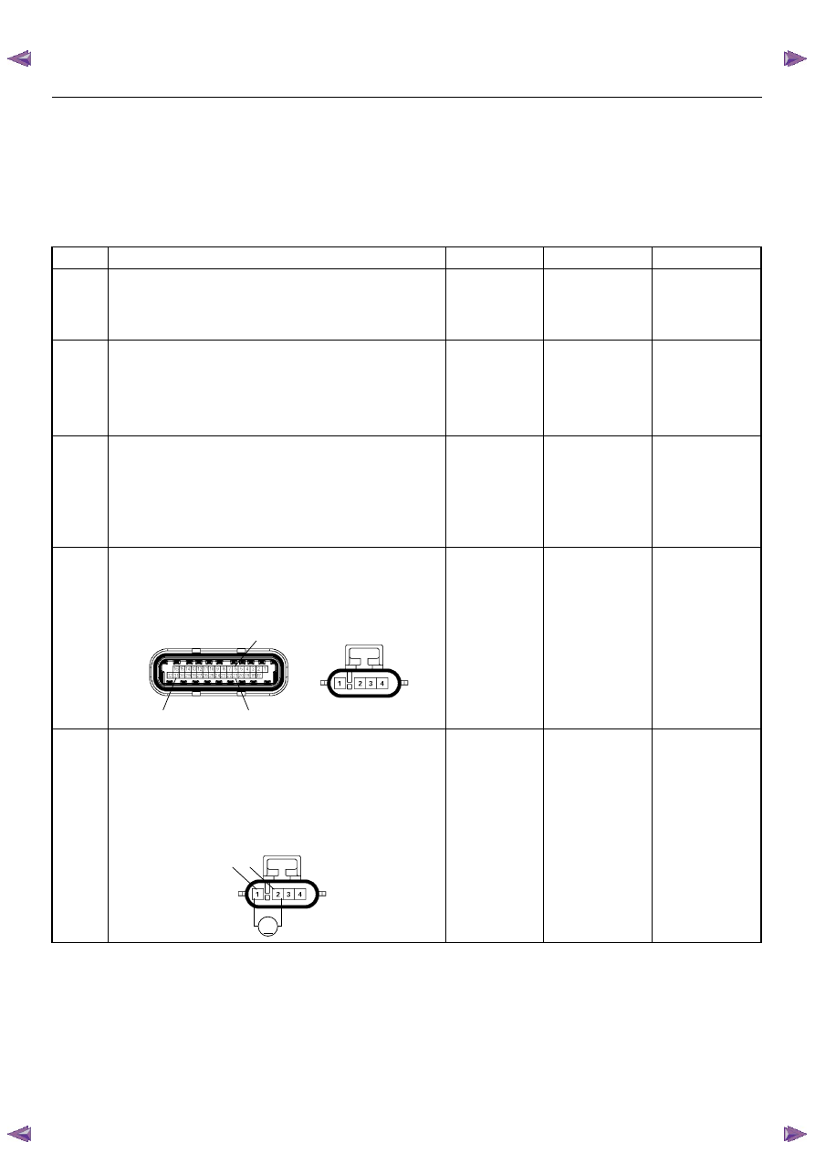
5
Using the DVM and check the O
2
sensor circuit.
1. Ignition “On”, engine “Off”.
2. Disconnect the O
2
sensor connector.
3. Check the circuit for open circuit.
Was the DVM indicated specified value?
Approximatly
450mV
Go to Step 7
Go to Step 6
C56(J2)
E77
31
21
6
V
2
1
E77
ENGINE DRIVEABILITY AND EMISSIONS
6E–161
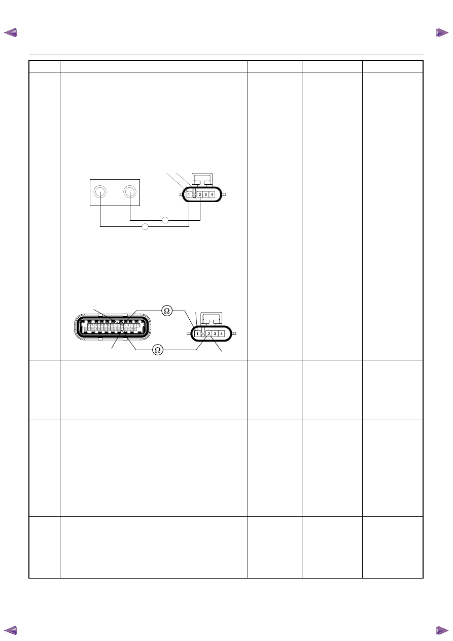
6
Using the DVM and check the O
2
sensor circuit.
Breaker box is available:
1. Ignition “Off”, engine “Off”.
2. Install the breaker box as type A. (ECM
disconnected) Refer to 6E-88 page.
3. Disconnect the O
2
sensor.
4. Check the circuit for open circuit.
Was the problem found?
Breaker box is not available:
1. Ignition “Off”, engine “Off”.
2. Disconnect the O
2
sensor connector and ECM
connector.
3. Check the circuit for open circuit.
Was the problem found?
—
Repair faulty
harness and
verify repair
Go to Step 13
7
1. Using the Tech 2, ignition “On” and engine “On”.
2. Monitor the “Manifold Absolute Pressure” in the
data display.
Does the Tech 2 indicate correct “Manifold Absolute
Pressure” in accordance with engine speed or
acceleration?
—
Go to Step 9
Go to Step 8
8
Remove the MAP sensor and check for the following
conditions.
• Objects blocking the air cleaner.
• Objects blocking the MAP sensor.
• Objects blocking the throttle valve.
• Vacuum leaking at intake duct.
• Vacuum leaking at throttle body.
If a problem is found, repair as necessary.
Was the problem found?
—
Verify repair
Go to Step 9
9
1. Using the Tech 2, ignition “On” and engine “On”.
2. Select the “Miscellaneous Test” and perform the
“IAC Control” in the “IAC System”.
3. Operate the Tech 2 in accordance with procedure.
Was the engine speed changed, when the IAC valve
is operating step by step?
—
Go to Step 11
Go to Step 10
Step
Action
Value(s)
Yes
No
J2-6
J2-21
Breaker Box
E-77
2
1
Ω
Ω
1
2
21
6
C56(J2)
E77
Нет комментариевНе стесняйтесь поделиться с нами вашим ценным мнением.
Текст