Isuzu KB P190. Manual — part 1156

7B1-18 MANUAL TRANSMISSION
4. Install a new gasket and gear control box assembly.
Install the harness clips and brackets and then
tighten four new gear control box bolts to the
specified torque.
Torque: 20 N
⋅⋅⋅⋅m (2.0 kgf⋅⋅⋅⋅m/14 lb⋅⋅⋅⋅ft)
261R300004
5. Install the O-ring (3) to the speedometer driven gear
bushing (2).
Install the driven gear to the speedometer driven
gear bushing (2).
6. Install the speedometer driven gear assembly to the
transmission rear cover.
Install the plate (1) to the transmission rear cover.
Torque: 15 N
⋅⋅⋅⋅m (1.5 kgf⋅⋅⋅⋅m/11 lb⋅⋅⋅⋅ft)
7. Install the speedometer sensor.
Torque: 27 N
⋅⋅⋅⋅m (2.8 kgf⋅⋅⋅⋅m/20 lb⋅⋅⋅⋅ft)
RTW77BSH008501
8. Install top gear bearing snap ring and counter front
bearing snap ring.
• Use a pair of snap ring pliers to install the snap
rings to the mainshaft and countershaft.
• The snap rings must be fully inserted into the
bearing snap ring groove.
9. Front cover with oil seal.
Front Cover Oil Seal Replacement
• Remove the oil seal from the front cover.
• Apply engine oil to a new oil seal, on the outer
circumference.
• Apply recommended grease to the oil seal lip.
• Use the oil seal installer 5-8840-0026-0 to install
the oil seal to the front cover.
220R3000020
10.
Install a new gasket and front cover to the
transmission case.
NOTE: Take care not to damage the oil seal.
Notes When Tightening the Bolt:
• After cleaning the bolt hole, air dry it thoroughly.
• After cleaning the screw face of a removed or new
bolt, dry it thoroughly. Apply recommended liquid
gasket (LOCTITE 242) or its equivalent before
tightening.
Tighten the six front cover bolts to the specified
torque.
Torque: 25 N
⋅⋅⋅⋅m (2.6 kgf⋅⋅⋅⋅m/19 lb⋅⋅⋅⋅ft)
MANUAL TRANSMISSION 7B1-19
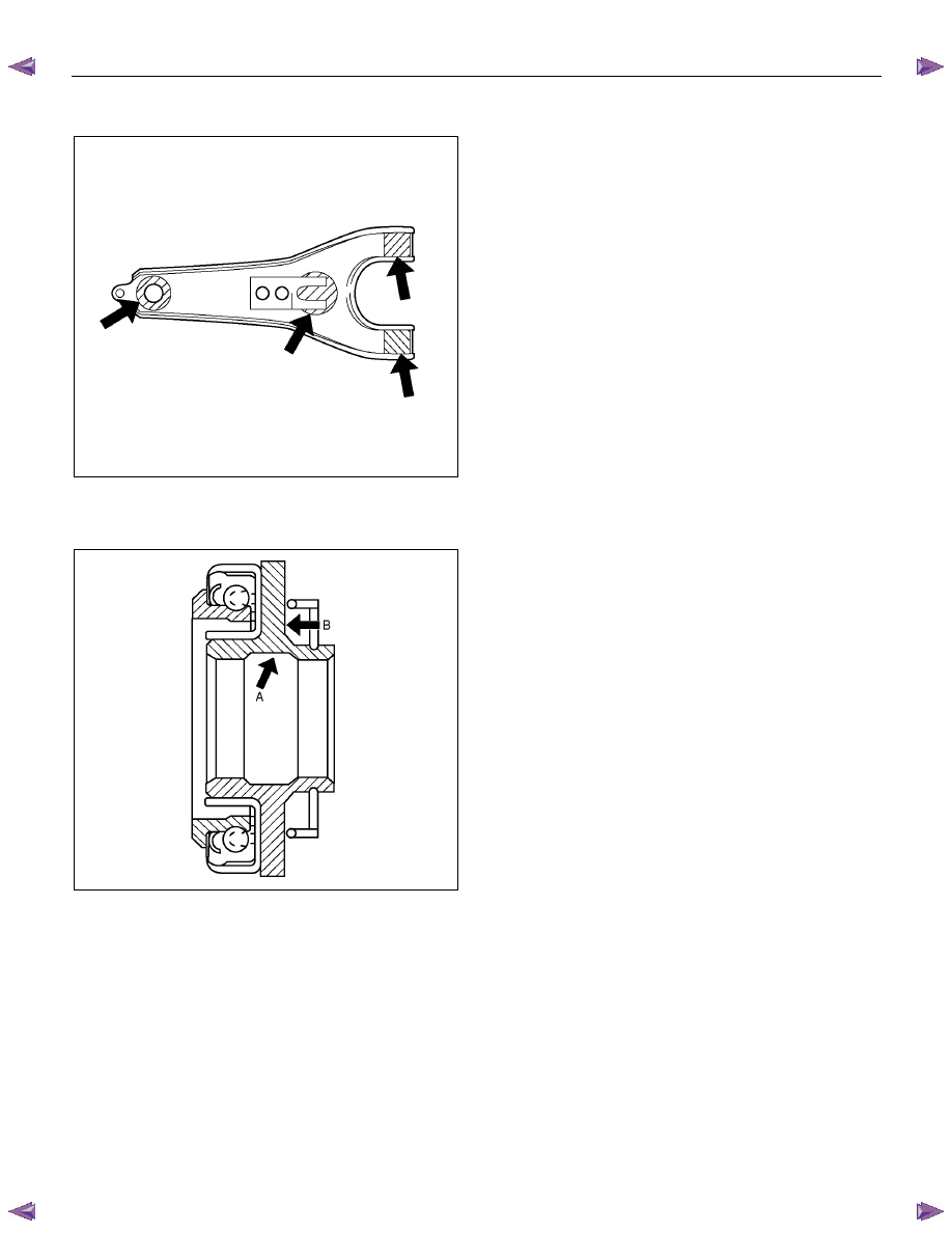
11. Apply molybdenum disulfide type grease to the
areas shown in the figure and install the shift fork.
F07L100026
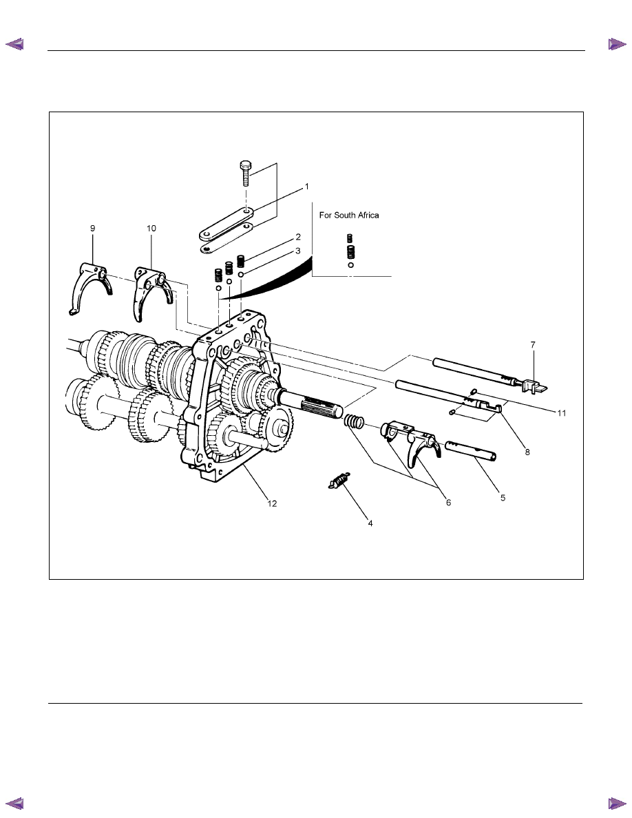
12. Pack the inside recess (A) and coat the back (B) of
the release bearing with molybdenum disulfide type
grease, as shown in the figure.
A07RW075
13. Install the release bearing on the front cover, joining
it to the shift frok.
7B1-20 MANUAL TRANSMISSION
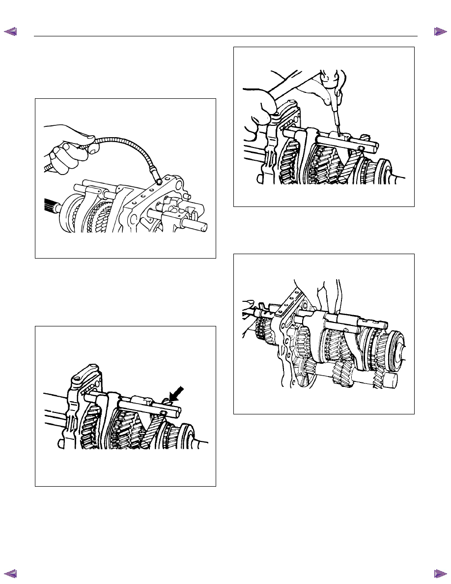
Intermediate Plate with Gear Assembly, Detent, Shift Arm, Shift Rod, and
Interlock Pin
Disassembled View
RTW57BLF000201
Legend
(1) Detent Spring Plate and Gasket
(7) 1st-2nd Shift Rod
(2) Detent Spring
(8) 3rd-4th Shift Rod
(3) Detent Ball
(9) 3rd-4th Shift Arm
(4) Spring
(10) 1st-2nd Shift Arm
(5) Rev-5th Shift Rod
(11) Interlock Pin
(6) Rev-5th Shift Arm and Reverse Inhibitor
(12) Intermediate Plate and Gear Assembly
MANUAL TRANSMISSION 7B1-21
Disassembly
1. Remove the detent spring plate and gasket, the
detent spring and detent ball.
Use a magnetic hand to remove the detent balls
from the intermediate plate.
220RS011
2. Remove the spring.
3. Remove the rev-5th shift rod, and rev-5th shift arm
and the reverse inhibitor.
Remove the 1st-2nd shift rod, 3rd-4th shift rod, 3rd-
4th shift arm, and 1st-2nd shift arm.
• Hold a round bar against the shift rod end.
230RS003
• Use a spring pin remover to remove the shift
arm spring pins from the shift arms, and the shift
rods.
230RS0004
• Be careful not to lose the interlock pins, when
pulling out the shift rod rearward.
The interlock pins are located between the
shifter rods in the intermediate plate.
230RS0005
• Remove the rev-5th, 1st-2nd and 3rd-4th shift
rods carefully.
4. Remove the interlock pin from the intermediate plate
and gear assembly.
Нет комментариевНе стесняйтесь поделиться с нами вашим ценным мнением.
Текст