Isuzu KB P190. Manual — part 1155
7B1-14 MANUAL TRANSMISSION
5. Install the starter. (Diesel engine only)
NOTE: Tighten the lower bolt temporarily.
After installing the fuel pipe assembly, tighten the bolt to
the specified torque.
Torque: 76 N
⋅⋅⋅⋅m (7.7 kgf⋅⋅⋅⋅m/56 lb⋅⋅⋅⋅ft)
6. Install the rear support rubber on the transmission
and tighten the nuts to the specified torque.
Torque: 52 N
⋅⋅⋅⋅m (5.3 kgf⋅⋅⋅⋅m/38 lb⋅⋅⋅⋅ft)
7.
Install the middle part of the transmission
crossmember and the bolts.
Tighten the nuts to the specified torque.
Torque: 67 N
⋅⋅⋅⋅m (6.8 kgf⋅⋅⋅⋅m/49 lb⋅⋅⋅⋅ft)
8. Install the engine rear mount nuts fixing on the
transmission crossmember.
Torque: 52 N
⋅⋅⋅⋅m (5.3 kgf⋅⋅⋅⋅m/38 lb⋅⋅⋅⋅ft)
Remove the transmission jack from transmission
side.
9. Apply grease to the top hole portion of the shift fork.
Install the slave cylinder and tighten the bolts to the
specified torque.
Torque: 76 N
⋅⋅⋅⋅m (7.7 kgf⋅⋅⋅⋅m/56 lb⋅⋅⋅⋅ft)
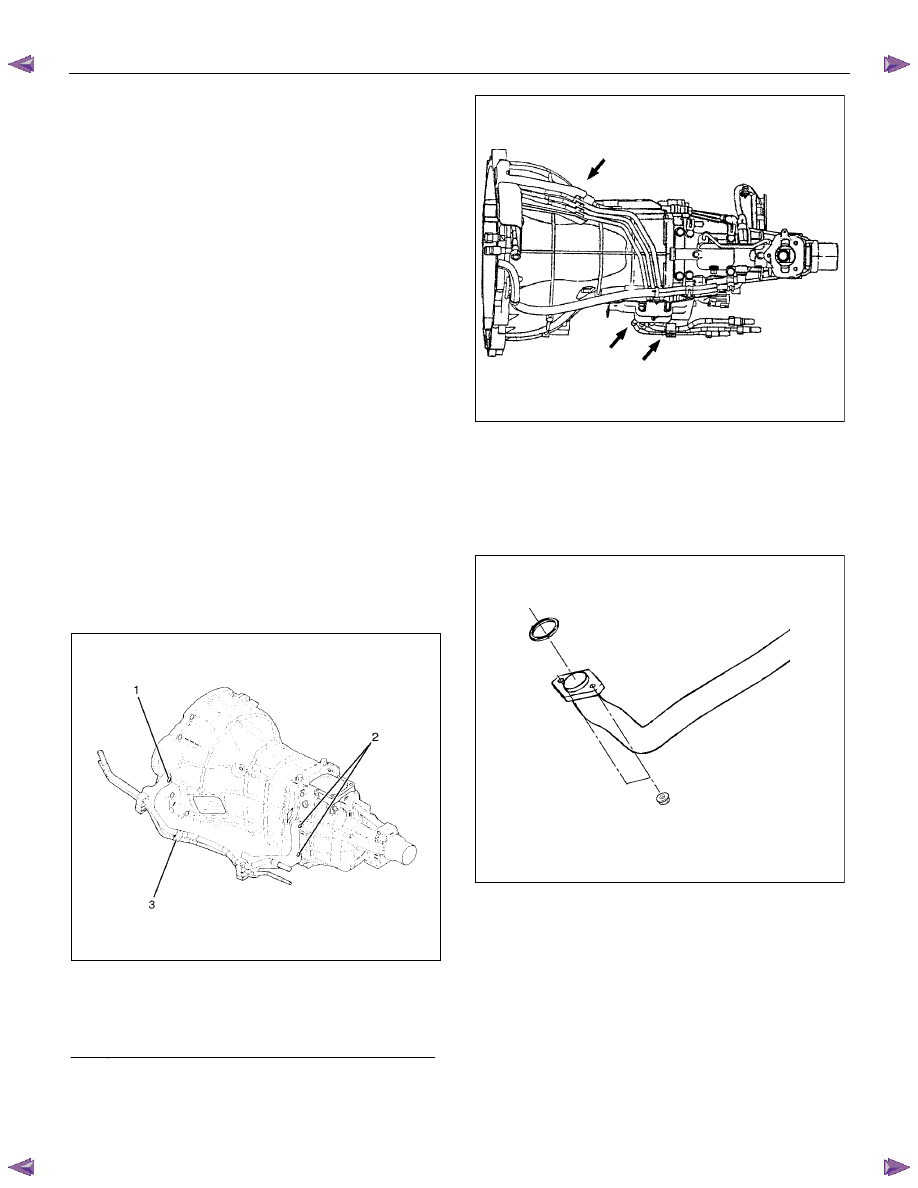
10. Install the fuel pipe brackets on the transmission.
Install the fuel pipe assembly to the fuel brackets.
Torque: Bolt & Nut
76 N
⋅⋅⋅⋅m (7.7 kgf⋅⋅⋅⋅m/56 lb⋅⋅⋅⋅ft)
Nut 37
N
⋅⋅⋅⋅m (3.8 kgf⋅⋅⋅⋅m/27 lb⋅⋅⋅⋅ft)
Diesel engine
220R300012
Legend
(1) Bolt
(2) Nut
(3) Fuel Pipe Assembly
C24SE
Scan-1
11. Connect the transmission harness connectors and
clip. Connector: neutral switch, car speed sensor,
and backup switch.
12. Tighten the exhaust pipe fixing nuts to the specified
torque. (Diesel engine only)
Torque: 67 N
⋅⋅⋅⋅m (6.8 kgf⋅⋅⋅⋅m/49 lb⋅⋅⋅⋅ft)
RTW67BSH000101
MANUAL TRANSMISSION 7B1-15
13. Install the rear propeller shaft.
Torque: 59 N
⋅⋅⋅⋅m (6.0 kgf⋅⋅⋅⋅m/43 lb⋅⋅⋅⋅ft)
14. Install the center bearing on crossemember.
Torque: 69 N
⋅⋅⋅⋅m (7.0 kgf⋅⋅⋅⋅m/51 lb⋅⋅⋅⋅ft)
15. Install the gear control lever.
Torque: 19 N
⋅⋅⋅⋅m (1.9 kgf⋅⋅⋅⋅m/14 lb⋅⋅⋅⋅ft)
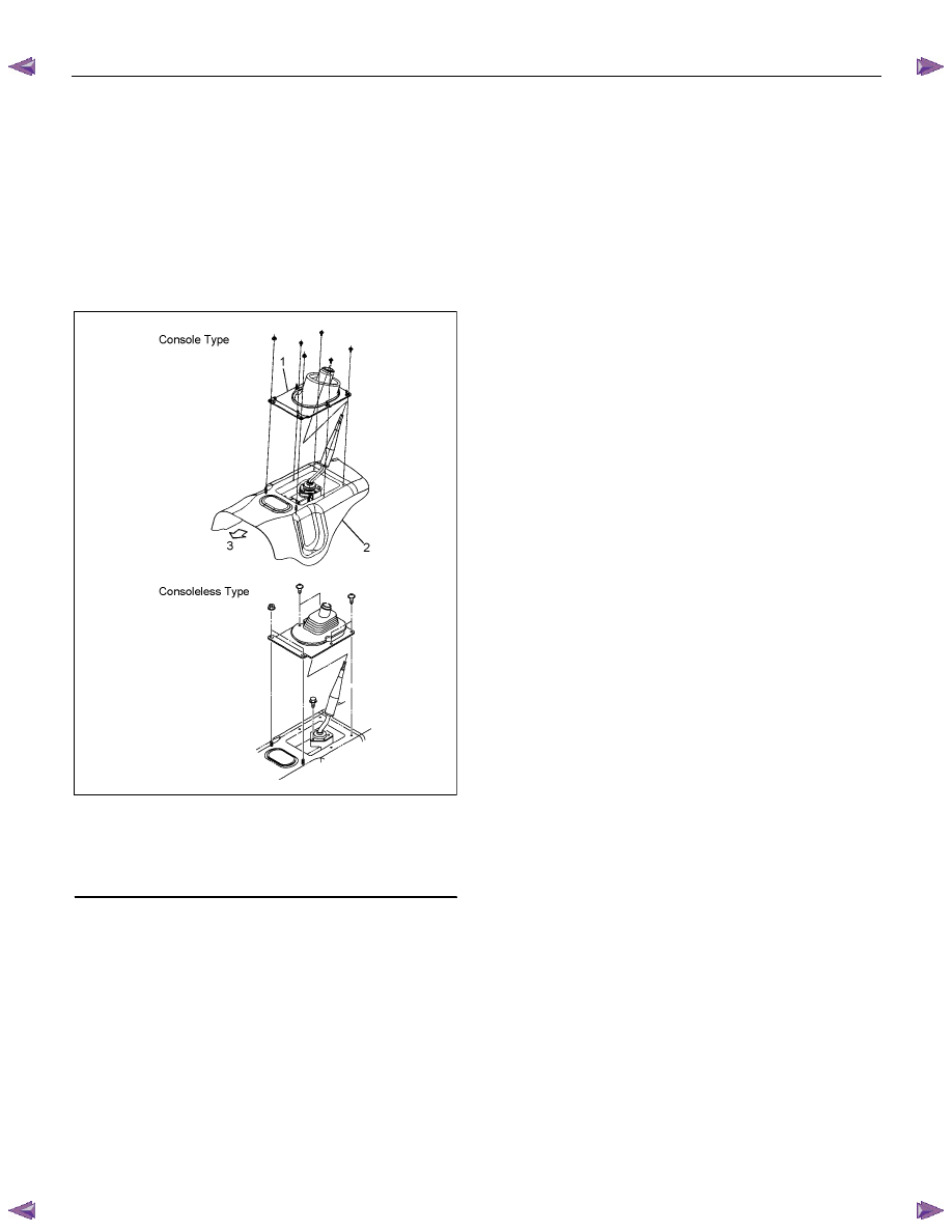
16. Install the grommet assembly.
Torque: Screw
1.4 N
⋅⋅⋅⋅m (0.14 kgf⋅⋅⋅⋅m/12 lb⋅⋅⋅⋅in)
Nut 7
N
⋅⋅⋅⋅m (0.7 kgf⋅⋅⋅⋅m/61 lb⋅⋅⋅⋅in)
RTW47BMH000101
Legend
(1) Grommet
Assembly
(2) Floor
Panel
(3) Front
17. Install the front floor console and the rear floor
console.
18. Install the gear control lever knob.
To the female thread portion, apply 3 - 4 drops of
adhesive (TB1344 or LOCTITE 222 or equiv.) and
tighten the transmission knob.
Torque: 9 N
⋅⋅⋅⋅m (0.9 kgf⋅⋅⋅⋅m/78 lb⋅⋅⋅⋅in)
After tightening to specified torque, rewrench the
knob until the direction of the shift pattern is in the
due positioned.
19. Connect the battery ground cable.

7B1-16 MANUAL TRANSMISSION
Transmission Case
Major Component
RTW77BLF003301
Legend
(1) Gear Control Box Assembly and Gasket
(7) Shift Fork and Cover: Diesel engine
(2) Speedometer Sensor and Driven Gear
(8) Counter Front Bearing Snap Ring
(3) Rear Cover Assembly
(9) Front Cover (with Oil Seal)
(4) Intermediate Plate with Gear Assembly
(10) Top Gear Bearing Snap Ring
(5) Transmission Case
(11) Release Bearing: C24SE
(6) Release Bearing (with Spring) : Diesel engine
(12) Shift Fork: C24SE
MANUAL TRANSMISSION 7B1-17
Disassembly
1. Clean the exterior of the unit with solvent.
2. Remove the drain plug from the transmission case
and drain the lubricant.
3. Remove the clutch release bearing with spring from
the transmission case.
4. Remove the shift fork, and boot.
5.
Remove the front cover and gasket from the
transmission case.
6. Remove the snap ring fixing counter front bearing.
7. Use a pair of snap ring pliers to remove the snap
ring fixing top gear bearing.
226RS001
8. Remove the speedometer sensor.
Remove the plate.
Remove the driven gear bushing and driven gear.
NOTE: Apply a reference mark to the driven gear
bushing before removal.
9. Remove the gear control box assembly.
10.
Remove the rear cover assembly from the
transmission case and intermediate plate.
11. Remove the intermediate plate with gear assembly
from the transmission case.
Reassembly
1.
Apply recommended liquid gasket (Three Bond
TB1215) or its equivalent to the transmission case,
intermediate plate and rear cover fitting surfaces.
2. Install the intermediate plate with the gear assembly
to the transmission case.
Pull out the top gear shaft until the ball bearing snap
ring groove protrudes from the transmission case
front cover fitting face.
Avoid subjecting the main shaft to sudden shock or
stress.
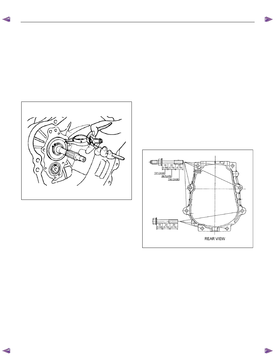
3.
Install the rear cover with an oil seal on the
intermediate plate, with the gear, by performing the
following steps.
• Cover the shaft splines with adhesive tape.
This will prevent damage to the oil seal lip.
• Tighten the transmission rear case bolts and
nuts to the specified torque.
Torque: 37 N
⋅⋅⋅⋅m (3.8 kgf⋅⋅⋅⋅m/27 lb⋅⋅⋅⋅ft)
mm (in)
RTW77BSH008601
Notes When Tightening the Bolt:
• After cleaning the bolt hole, air dry it thoroughly.
• After cleaning the screw face of a removed or new
bolt, dry it thoroughly. Apply recommended liquid
gasket (LOCTITE 242) or its equivalent, before
tightening.
Нет комментариевНе стесняйтесь поделиться с нами вашим ценным мнением.
Текст