Isuzu KB P190. Manual — part 1035
UNIT REPAIR (AW30–40LE)
7A4–5
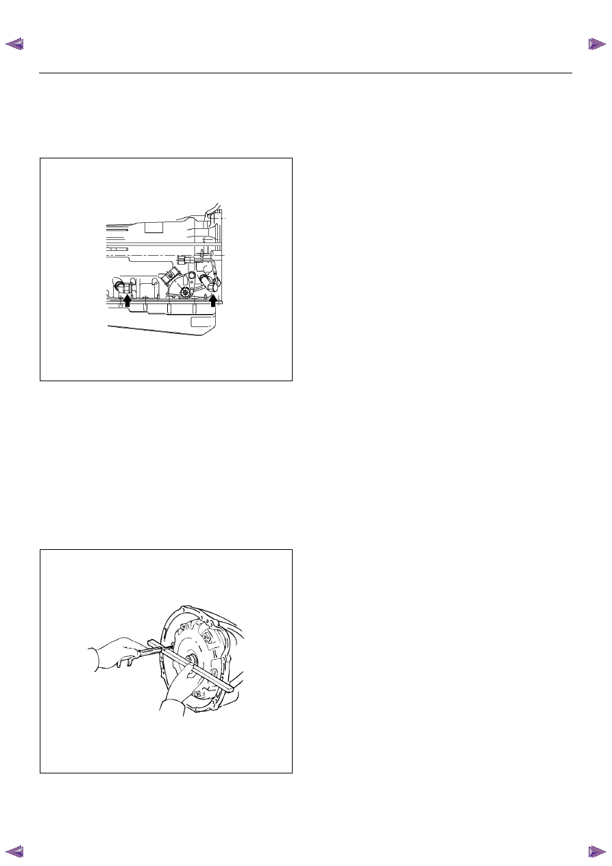
6. Install the elbow.
• Coat new O-rings with ATF, install them to the two
elbows.
• Install the two elbows as shown in the figure.
Torque: 29 N·m (3.0 kgf·m/22 Ib·ft)
RTW77ASH003601
7. Install the select lever.
8. Install the output revolution sensor (4
×
2).
9. Install the output revolution sensor (4
×
4).
10. Install the input revolution sensor.
11. Install the breather hose.
12. Install the torque converter.
Using calipers and a straightedge, measure the
distance from the installed surface of the
transmission housing to top of the torque converter
nut.
Correct distance: 13.5 mm (0.53 in)
240RY00005
7A4–6
UNIT REPAIR (AW30–40LE)
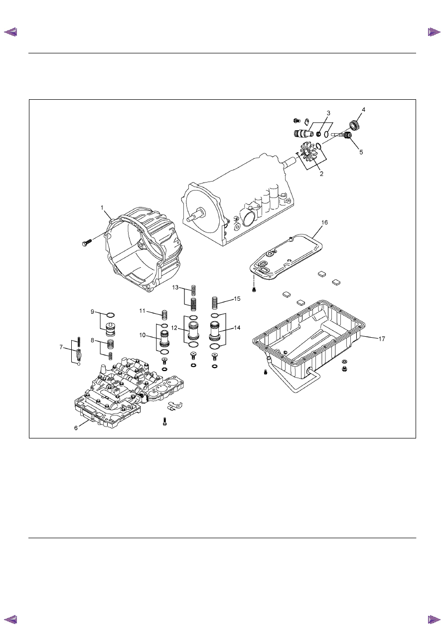
Major Components (2)
Major Componets (2) and Associated Parts
RTW77ALF001701
EndOFCallout
Legend
(1) Converter housing
(2) Snap ring, rotor, key
(3) Speedometer shaft sleeve
(4) Speedometer drive gear
(5) Speedometer driven gear
(6) Valve body
(7) Check valve, spring, ball
(8) Spring
(9) Accumulator piston (C–0), O-ring
(10) Accumulator piston (B–0), O-ring
(11) Spring
(12) Accumulator piston (C–2), O-ring
(13) Spring
(14) Accumulator piston (B–2), O-ring
(15) Spring
(16) Oil strainer assembly
(17) Oil pan
UNIT REPAIR (AW30–40LE)
7A4–7
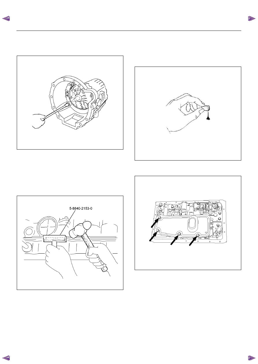
Disassembly
1. Remove the six bolts and remove the converter
housing.
240R200022
2. Remove the oil pan.
NOTE: Do not turn over the transmission as this will
contaminate the valve body with foreign materials in the
bottom of the oil pan.
• Remove the nineteen bolts.
• Remove oil pan by lifting the transmission case.
Oil pan seal cutter: 5-8840-2153-0
RUW37ASH002901
3. Examine particles in oil pan.
• Remove the magnet and use it to collect any
steel chips.
• Look carefully at the chips and particles in the oil
pan and on the magnet to anticipate what type of
wear you will find in the transmission:
Steel (magnetic) . .. bearing, gear and clutch
plate wear
Brass (non-magnetic)... bushing wear
240RY00008
4. Remove the oil strainer assembly.
Remove four bolts holding the oil strainer.
244RY00003
7A4–8
UNIT REPAIR (AW30–40LE)
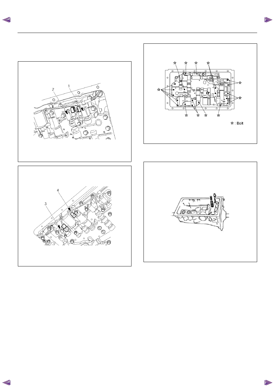
5. Remove the valve body.
• Disconnect the connectors from the solenoid S1
(1), S2 (2), lock-up solenoid (3) and pressure
control solenoid (4).
249RY00011
249RY00012
• Remove the twenty bolts from valve body.
244R200078
6. Remove the check valve and spring.
7. Remove two springs from C–0 accumulator piston.
240RY00028
Нет комментариевНе стесняйтесь поделиться с нами вашим ценным мнением.
Текст