Isuzu KB P190. Manual — part 1036
UNIT REPAIR (AW30–40LE)
7A4–9
8. Remove the accumulator piston (B–2).
9. Remove the accumulator piston (C–2).
• Remove accumulator pistons and springs from
transmission case.
240RY00010
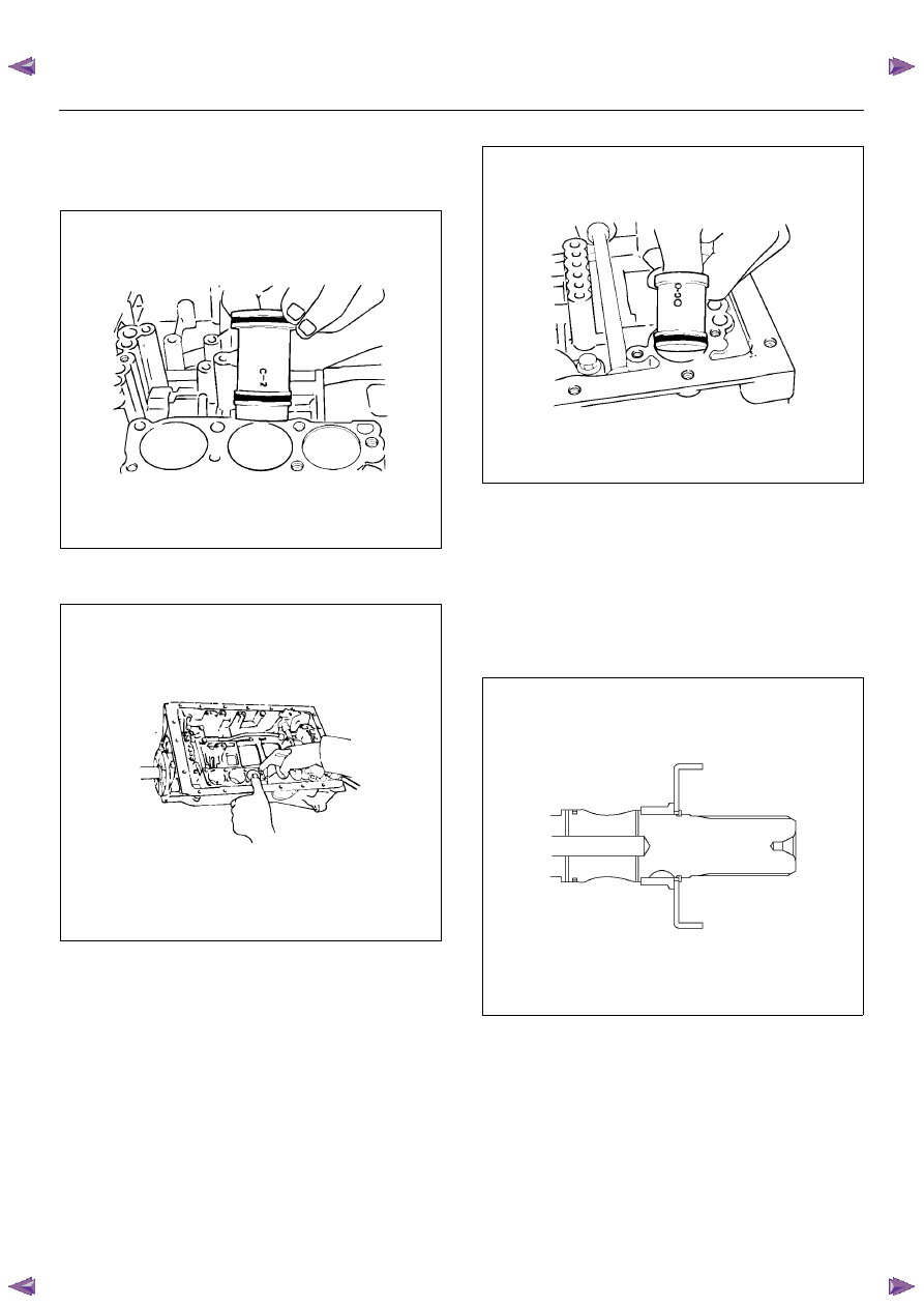
10. Applying compressed air to the oil hole, remove the
B–0 accumulator piston and spring.
240RY00011
11. Remove the C–0 accumulator piston.
240RY00012
12. Remove the second brake drum gasket.
13. Remove the solenoid wiring.
• Turn over transmission, remove the solenoid
wiring stopper plate from the case.
• Pull the wiring out of the transmission case.
14. Remove the snap ring, rotor and key (4
×
4).
• Remove the snap ring from the output shaft.
• Remove the rotor and key.
247R200002
15. Remove the snap ring, speedometer sensor drive
gear and ball (4
×
2).
• Remove the snap ring from the output shaft.
• Remove the speedometer sensor drive gear, and
ball.
7A4–10
UNIT REPAIR (AW30–40LE)
16. Remove the spacer, rotor, key and snap ring (4
×
2).
• Remove the spacer, rotor and key.
• Remove the snap ring from the output shaft.
247L100001
Reassembly
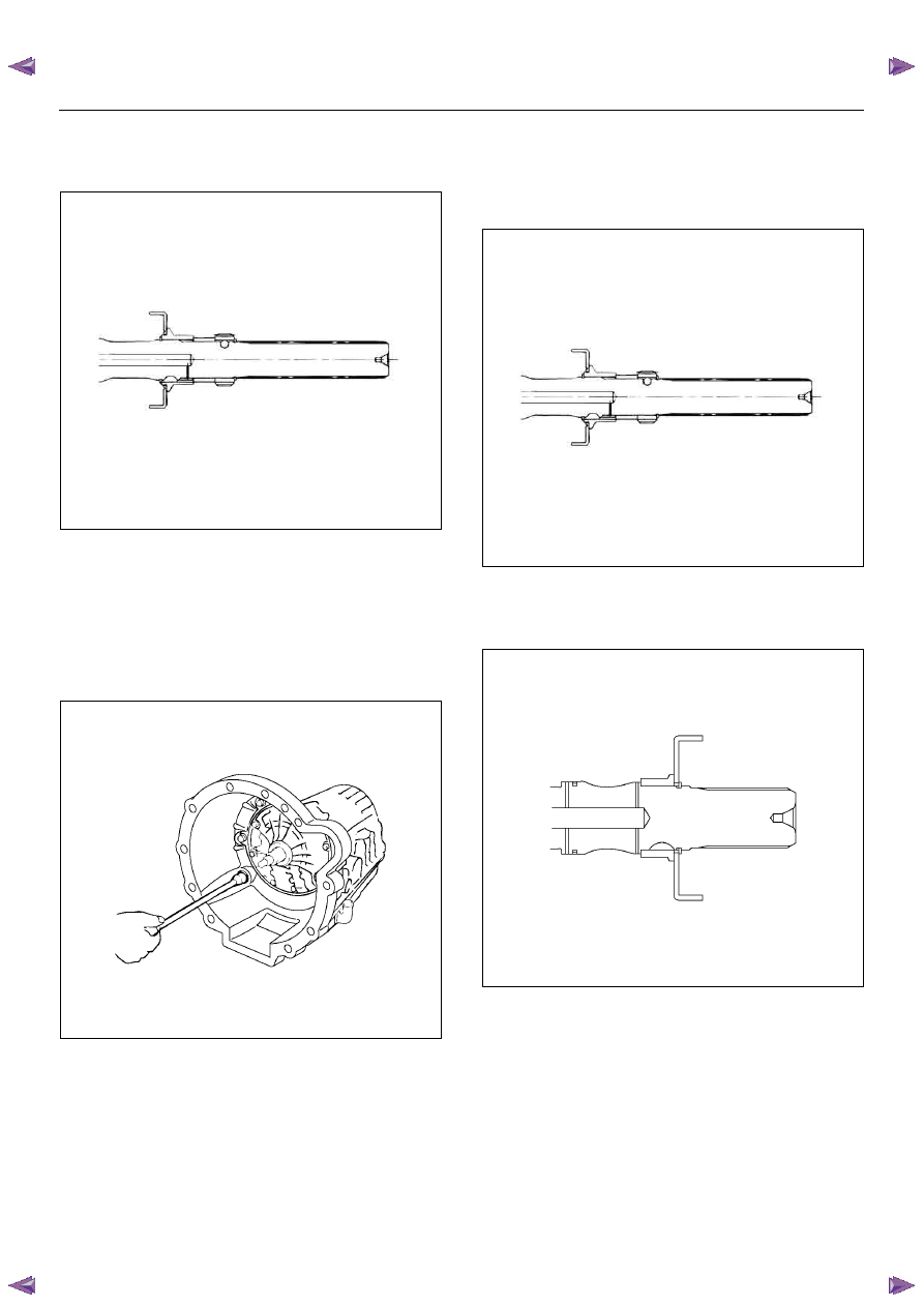
1. Install the converter housing.
Torque:
M10 – 34 N·m (3.5 kgf·m/25 lb·ft)
M12 – 57 N·m (5.8 kgf·m/42 lb·ft)
240R200022
2. Install the snap ring, key and rotor (4
×
2).
• Install the snap ring to the output shaft.
• Install the key and rotor.
3. Install the spacer, ball, speedometer sensor drive
gear and snap ring (4
×
2).
• Install the spacer, ball and speedometer sensor
drive gear.
• Install the snap ring to the output shaft.
247L100001
4. Install the key, rotor and snap ring (4
×
4).
• Install the key and rotor.
• Install the snap ring to the output shaft.
247R200002
UNIT REPAIR (AW30–40LE)
7A4–11
5. Install the second brake drum gasket.
• Install a new second brake drum gasket to the
transmission case.
240RY00013
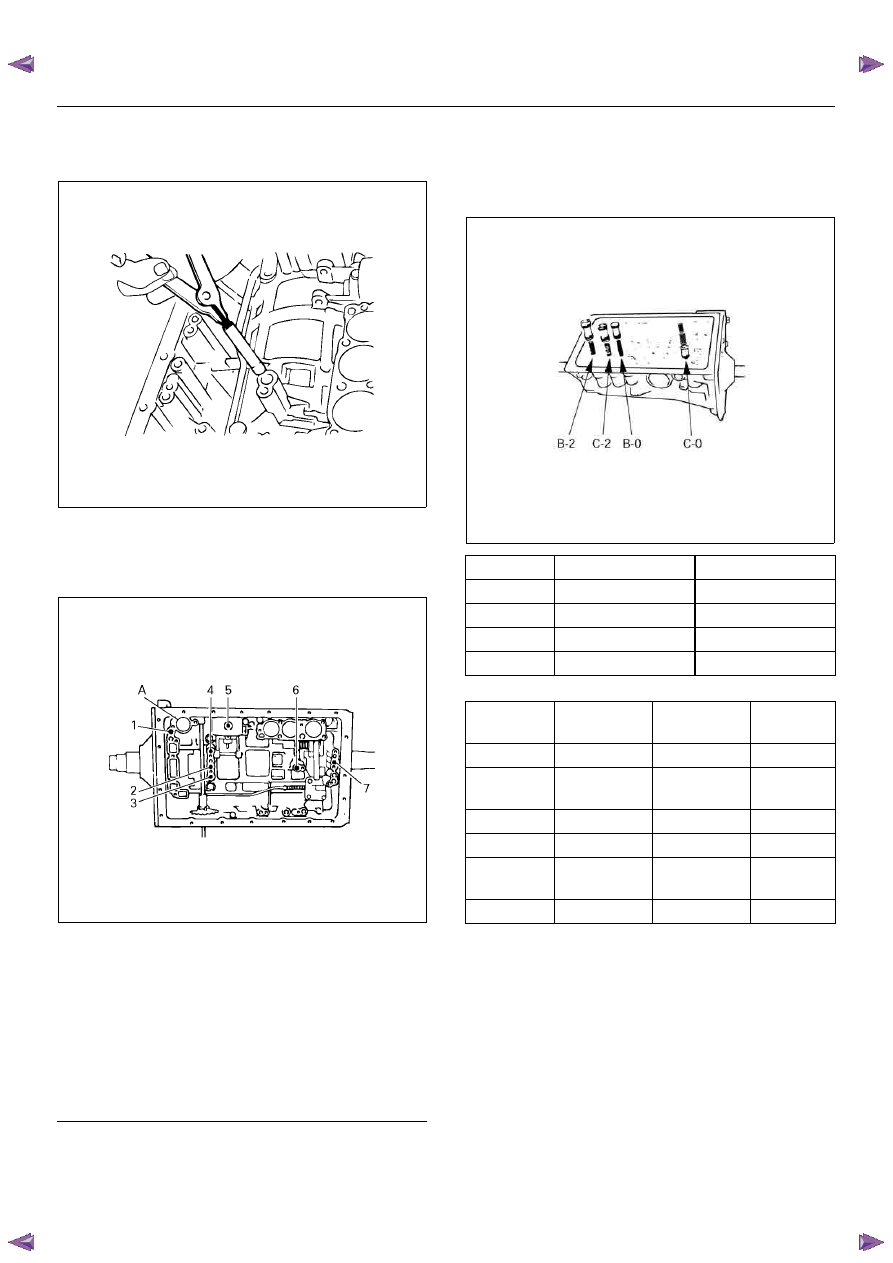
6. Individual piston operation inspection.
Check for the sound of operation while injecting
compressed air into the oil hole indicated in the
figure.
240RY00014
EndOFCallout
NOTE: When inspecting the direct clutch, check with
the C–0 accumulator piston hole closed. If there is no
noise, disassemble and check the condition of the parts.
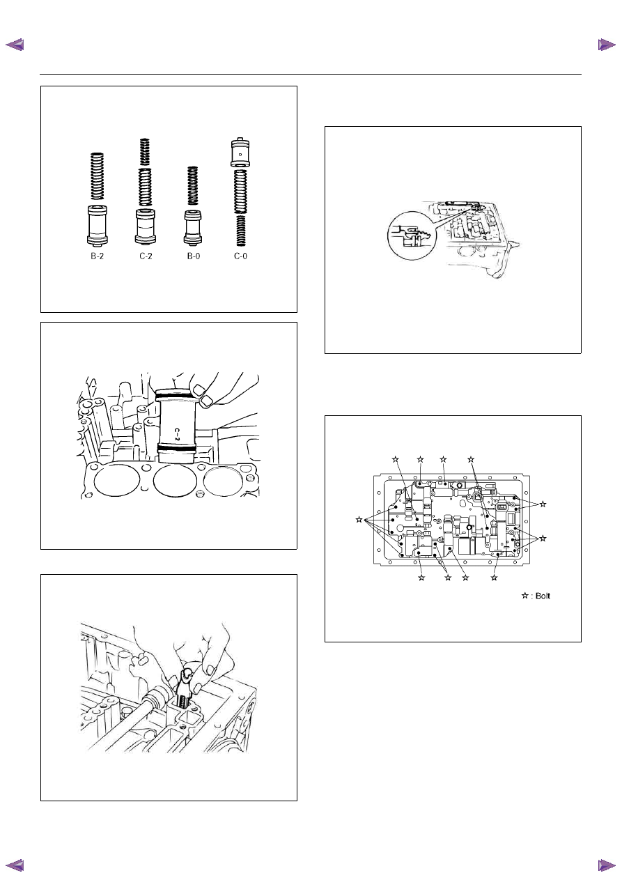
7. Install the accumulator pistons.
• Coat the O–ring with ATF and install it to the
piston.
Install the three springs and four accumulator
pistons to the bore as shown in th figure.
240RY00027
mm (in)
Legend
(1) OD direct clutch
(2) Direct clutch
(3) Forward clutch
(4) OD brake
(5) Second coast brake
(6) Second brake
(7) First and reverse brake
(A) C–0 Accumulator piston hole
Piston
Outer diameter
Height
B–2
36.8 mm (1.449 in)
62.5 mm (2.461 in)
C–2
36.8 mm (1.449 in)
56.6 mm (2.228 in)
B–0
31.8 mm (1.252 in)
52.0 mm (2.047 in)
C–0
29.8 mm (1.173 in)
44.0 mm (1.732 in)
Spring
Free length
Outer
diameter
Color
B–2
75.8 (2.984)
20.1 (0.791)
PURPLE
C–2
(Outer)
64.0 (2.520)
20.3 (0.799)
WHITE&
PINK
C–2 (Inner)
42.1 (1.657)
14.7 (0.579)
PINK
B–0
62.0 (2.441)
16.0 (0.630)
GREEN
C–0
(Outer)
74.6 (2.937)
20.9 (0.823)
ORANGE
C–0 (Inner)
46.0 (1.811)
14.0 (0.551)
YELLOW
7A4–12
UNIT REPAIR (AW30–40LE)
240RY00029
240RY00010
8. Install new check valve and spring.
240RY00016
9. Install the valve body.
• Align the groove of the manual valve to the pin of
the lever.
240RY00017
• Install the twenty bolts.
NOTE: Each bolt length (mm) is indicated in the figure.
Torque: 10 N·m (1.0 kgf·m/87 lb·in)
244R200078
Нет комментариевНе стесняйтесь поделиться с нами вашим ценным мнением.
Текст