Isuzu KB P190. Manual — part 1067
CONSTRUCTION AND FUNCTION 7A1-29
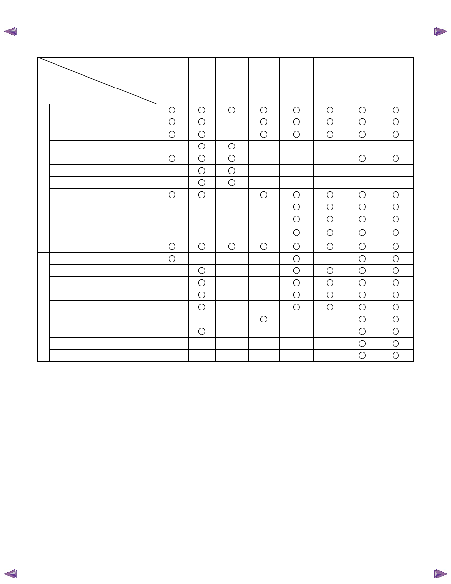
CONTROL ITEM, INPUT AND OUTPUT
Control item
Item
Line
pressure
control
Gear
shift
control
Shift
pattern
selection
Lock-up
control
Direct
electronic
shift
control
(DECS)
Learning
control
Fail-safe
function
Self-
diagnosis
function
Speed sensor
Turbine sensor
Engine speed sensor
Brake switch
Inhibitor switch
Mode select switch
4L switch (4WD Only)
ATF thermo sensor
High clutch oil pressure switch
2-4 brake oil pressure switch
Low & Reverse brake oil pressure
switch
Input
Accelerator Pedal position sensor
Line pressure solenoid
Low clutch solenoid
High clutch solenoid
2-4 brake solenoid
Low & Reverse brake solenoid
Lock-up solenoid
Shift pattern indicator lamp
ATF temperature indicator lamp
O
u
tput
Check trans indicator lamp
7A1-30 CONSTRUCTION AND FUNCTION
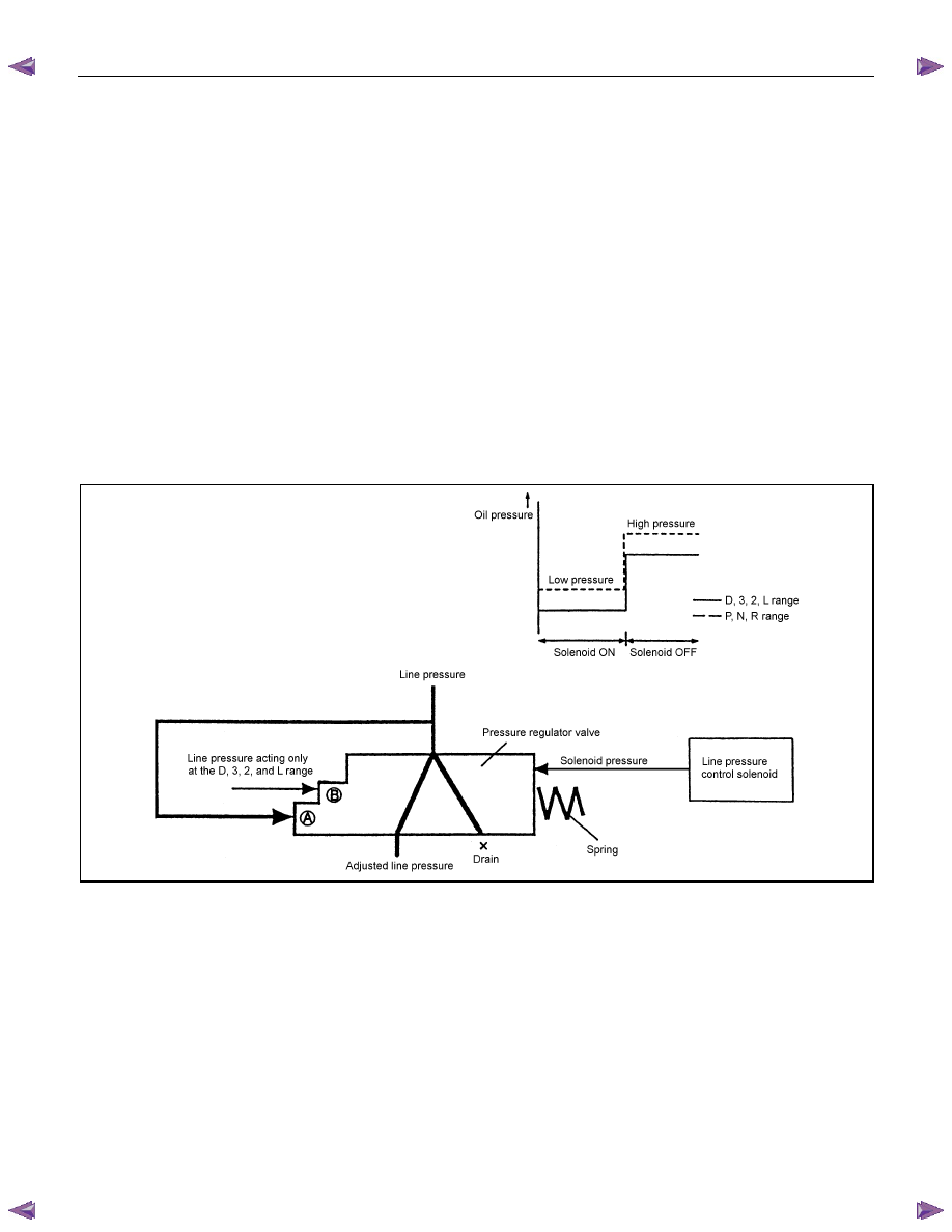
LINE PRESSURE CONTROL
•
The TCM drives the ON/OFF type line pressure solenoid based on the APP opening, vehicle speed,
turbine rotational speed, ATF temperature and shift position signal. The ON/OFF type line pressure
solenoid is actuated, and switches the line pressure to a high or low pressure number appropriate to the
situation.
•
The line pressure generated by the oil pump acts on the point A of the pressure regulator valve. When
the pressure control solenoid is turned ON by the signal from the TCM, the solenoid pressure does not
act. The line pressure is adjusted to match the spring force acting on the right side of the pressure
regulator valve.
•
When the pressure control solenoid is turned OFF, the solenoid pressure acts so that the line pressure is
adjusted to match the spring force acting on the right side of the pressure regulator valve.
•
As a result, the line pressure is adjusted to be low when the pressure control solenoid is ON and to be
high when the pressure control solenoid is OFF.
•
In position D, 3, 2 and L, the line pressure through the oil pressure circuit acts onto the point B of the
pressure regulator valve. The pressure regulator valve moves so as to increase the pressure to be
drained, so that the line pressure is adjusted to be lower than the P, N, and R position by the difference of
area at the point B.
Figure 50. Line Pressure Control
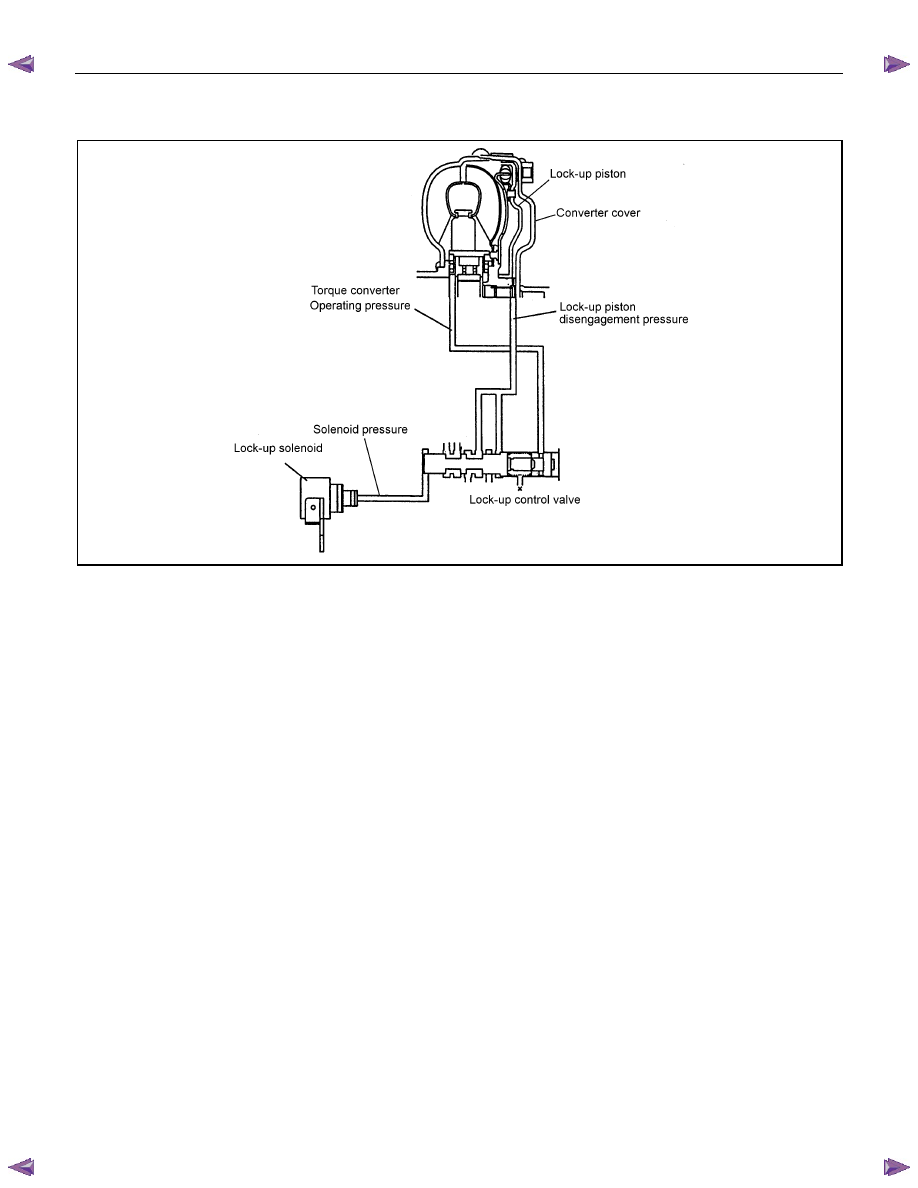
LOCK-UP CONTROL
•
The lock-up solenoid adjusts the pressure and controls the lock-up based on the pre-set lock-up point,
according to the vehicle speed, APP opening, engine rotations, turbine rotations and ATF temperature
input signal, based on the signal from the TCM.
•
Smooth lock-up control is employed to engage or disengage the clutch smoothly at the time of lock-up on
or off.
•
When the oil temperature is low (20
°
C or less), lock-up is disengaged even though the vehicle is at the
lock-up speed.
•
The lock-up is disengaged also when the APP is closed.
•
When the TCM determines the lock-up engagement, the DUTY ratio to supply power to the lock-up
solenoid is gradually increased (5% to 95%) and the oil between the lock-up piston and converter cover is
gradually drained.
CONSTRUCTION AND FUNCTION 7A1-31
As a result, the lock-up piston is fitted slowly to the converter cover under pressure securing smooth lock-
up engagement.
Figure 51. Lock-up Control
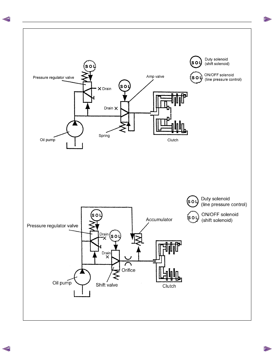
DIRECT ELECTRIC SHIFT CONTROL (DESC)
Feature
•
Based on each switch signal (low & reverse brake pressure, 2-4 brake pressure & high clutch pressure)
and each sensor signal (turbine sensor, speed sensor, engine speed signal & APP position signal), the
duty cycle type solenoid adjusts the clutch pressure to match the engine load and vehicle travel
conditions. Controlling the engagement and disengagement of the clutch and brake pressure is directly
and accurately controlled via TCM, which is different to the previous accumulator type.
Operation
•
Instead of the previous system (on/off type of shift solenoid and shift valve), the combination of the duty
cycle type solenoid and the amplifier (Amp) valve are used to adjust the clutch pressure to match the
engine load and vehicle travel conditions, based on the signal from the TCM. Also, the pressure switch
provided in the oil passage of the control valve transmits the oil pressure condition (at that time) to TCM,
enabling the engagement and disengagement control of the clutch and brake to be directly and finely
carried out.
•
When the gear is shifted from the 2nd to 3rd, 3rd to 4th (O/D), 4th (O/D) to 3rd and 3rd to 2nd, the clutch
pressures on the engagement side and disengagement side are simultaneously controlled.
As a result, engine racing or clutch drag is prevented which enables a smooth and quick shift response.
7A1-32 CONSTRUCTION AND FUNCTION
Direct Electric Shift Control
Previous Model
Figure 52. Direct Electric Shift Control (DESC)
Нет комментариевНе стесняйтесь поделиться с нами вашим ценным мнением.
Текст