Isuzu KB P190. Manual — part 1066
CONSTRUCTION AND FUNCTION 7A1-25
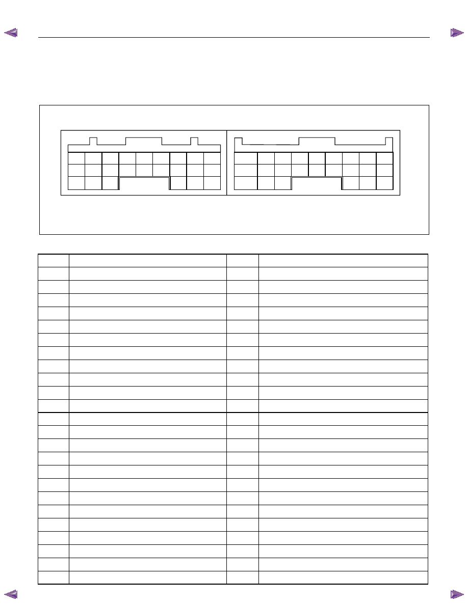
TRANSMISSION CONTROL MODULE (TCM)
•
The TCM is fitted on the side of the brake pedal via two stud bolts.
•
The TCM judges the line pressure, gear shifting point and lock-up operation based on electrical signals
from switches and sensors, and sends the appropriate signals to solenoids.
B9 B8 B7 B6 B5 B4 B3 B2 B1
A9
A8 A7 A6 A5 A4 A3 A2 A1
B18 B17 B16 B15 B14 B13 B12 B11 B10
A18 A17 A16 A15 A14 A13 A12 A11 A10
B24 B23 B22
B21 B20 B19
A24 A23 A22
A21 A20 A19
Connect to White Connector Connect to Grey Connector
Figure 49. Pin Assignment
Pin No.
Pin Assignment
Pin No.
Pin Assignment
B1
2-4 Brake Oil Pressure Switch
A1
V BATT (Battery Back-up Power Supply)
B2
2 Position Switch
A2
P Position Switch
B3
Turbine Sensor
A3
Brake Switch
B4
ATF Thermo Sensor
A4
3rd Start Indicator Lamp
B5
Ground
A5
K-Line Signal (Tech 2 Serial Communication)
B6
Low & Reverse Brake Duty Solenoid
A6
No Connection
B7
2-4 Brake Duty Solenoid
A7
Engine Speed Sensor
B8
High Clutch Duty Solenoid
A8
No Connection
B9
Low Clutch Duty Solenoid
A9
No Connection
B10
N Position Switch
A10
Vehicle Speed Sensor Out (2WD Only)
B11
D Position Switch
A11
3rd START Select Switch
B12
Low & Reverse Brake Oil Pressure Switch
A12
4L Mode Switch (4WD Only)
B13
Vehicle Speed Sensor
A13
No Connection
B14
ATF Thermo Sensor Ground
A14
No Connection
B15
No Connection
A15
No Connection
B16
No Connection
A16
Accelerator Pedal Position Sensor
B17
Lock-up Duty Solenoid
A17
3 Position Switch
B18
Vign (Ignition Power Supply)
A18
DIAG Switch (Test Switch)
B19
R Position Switch
A19
A/T OIL TEMP Indicator Lamp
B20
High Clutch Oil Pressure Switch
A20
CHECK TRANS Indicator Lamp
B21
L Position Switch
A21
POWER DRIVE Indicator Lamp
B22
Ground (Shift Solenoid)
A22
No Connection
B23
Line Pressure Solenoid
A23
No Connection
B24
Vign (Ignition Power Supply)
A24
POWER DRIVE Select Switch
7A1-26 CONSTRUCTION AND FUNCTION
CONTROL MECHANISM
CONTENT OF FUNCTION AND CONTROL
Item
Description
Line pressure control
TCM issues a signal according to vehicle travel, engine load and other conditions, which
drives the ON/OFF type line pressure solenoid to switch the line pressure to high or low
pressure.
The line pressure solenoid is switched to the low pressure side when the solenoid is turned
ON (power supplied) and to the high pressure side when turned OFF (no power supplied).
In the forward travel position (D, 3, 2, L position), the line pressure decreases lower than
that in the P, N, and R position through the oil pressure circuit.
Gear shift control
The TCM issues a shift solenoid drive signal based on the traveling mode switch, inhibitor
switch, the vehicle speed, the APP opening and other input signals, to control the optimum
gear position automatically.
Shift features have been set up to the TCM; the normal mode is suited to normal travel, and
the power mode is used when the vehicle is loaded or the speed accelerated.
In addition, shift features used only for high oil temperature, hill climbing, and downward
travel have been set up to the TCM. These are automatically switched depending on the
travel conditions.
When the oil temperature is low (10
°
C or less), shifting up from the third speed to the fourth
speed is prohibited by the gear shift control.
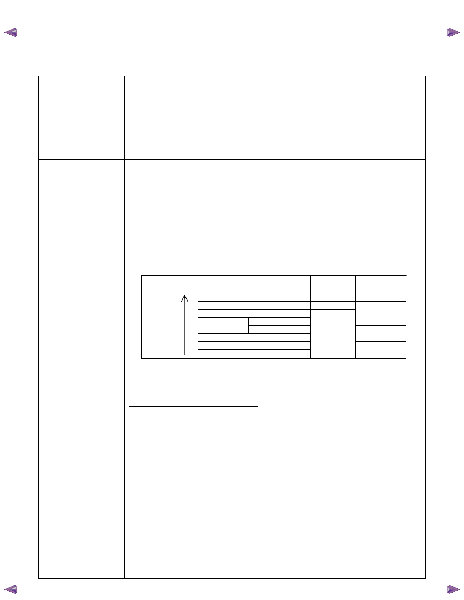
Shift pattern selection
control
The TCM selects the following shift pattern according to a vehicle condition.
Selection
Priority
Shift Pattern
3rd Start
Lamp
Power Drive
Lamp
High
High Temperature
OFF OFF
3rd Start
ON
4L
Power SW Off
OFF
Down Slope
Power SW On
Power
ON
Up Slope
Low
Normal
OFF
OFF
- High temperature mode -
High temperature mode setting condition
ATF temperature: 122
°C or more
Above condition is met for 10.16 seconds.
High temperature mode cancel condition
ATF temperature: 115
°C or less
Above condition is met for 10.16 seconds.
-NOTE-
High temperature mode may be activated with driving conditions other than the setting
conditions stated, in order to protect Automatic Transmission from thermal damage.
- 3rd start mode -
3rd start mode setting condition
3rd start switch: On
→ Off (Pushed)
Vehicle speed: 11km/h or less.
ATF temperature: 115
°C or less.
APP position: 8% or less.
Select lever position: D position
Above conditions are all met at the same time.

CONSTRUCTION AND FUNCTION 7A1-27
Item
Description
3rd start mode reset condition
3rd start switch: On
→ Off again(Pushed again)
Vehicle speed: 34km/h or more
Select lever position: Other than D position
At least, one of above conditions is met.
- 4L mode -
4L mode setting condition
4L switch: On
Vehicle speed: 5km/h or more
Above conditions are all met at the same time.
4L mode reset condition
4L switch: Off
Vehicle speed: Less than 5km/h
Above conditions are all met at the same time.
- Down slope mode -
Down slope mode setting condition
Brake switch: On
Accelerator pedal condition: Released for 2 seconds or more.
Select lever position: D or 3 position
Vehicle speed: More than 60km/h
Increment of vehicle speed: More than 1km/h per second
Above conditions are all met at the same time.
Down slope mode reset condition
Accelerator pedal condition: Depressed
Select lever position: Other than D or 3 position
At least, one of above conditions is met.
- Power Mode -
When the power drive switch is On the shift pattern change is performed by 1
– 4 speed
based on shift diagram set as power pattern
.
- Up slope mode -
Up-slope reasoning value is calculated from the average APP angle and the average
acceleration. Otherwise, up-slope reasoning value is calculated from the vehicle speed.
TCM chooses up-slope mode when the former is bigger than the latter.
Lock-up control
The lock-up solenoid adjusts the pressure to control the lock-up according to the signal
from the TCM. This signal is based on the vehicle speed, APP opening and other input
signals based on the pre-set lock-up point.
Smooth lock-up control engages and disengages the clutch smoothly at the time of lock-up.
When the oil temperature is low (20
°
C or less), lock-up is prohibited even when the vehicle
is at a lock-up speed.
The lock-up is also disengaged when the APP is closed.
Direct electronic shift
control (DESC)
The duty cycle type solenoid is used for each clutch and brake. The solenoid adjusts the
clutch pressure to suit the engine load and vehicle traveling condition based on the signal
from the TCM. The pressure switch provided in the control valve oil passage sends the oil
pressure condition to the TCM, which controls the disengagement or engagement of the
clutch and brake directly and finely.

7A1-28 CONSTRUCTION AND FUNCTION
Item
Description
Learning function
The learning function is provided to correct the oil pressure control timing to engage or
disengage the clutch optimally in order to compensate changes of the engine performance
and changes of the transmission with time. It is controlled to bring the shift time closer to
the value pre-set to the TCM.
Fail-safe function
In the case of a malfunction of the vehicle speed sensor, APP sensor, all solenoids or the
inhibitor switch, TCM automatically begins fail-safe control to minimize effects on driving.
The gear is fixed in 3rd gear and the power supply to the solenoid is shut off so that the
solenoid does not work. Lock up clutch is disengaged in this mode.
Self-diagnosis function
Parts required for controlling the automatic transmission are provided with a self-diagnosis
function. When any trouble occurs, the check trans indicator lamp blinks to warn the driver.
The trouble code is memorized in the TCM.
Нет комментариевНе стесняйтесь поделиться с нами вашим ценным мнением.
Текст