Isuzu KB P190. Manual — part 589
6E–186
ENGINE DRIVEABILITY AND EMISSIONS
DIAGNOSTIC TROUBLE CODE (DTC) P0351 IGNITION 1 CONTROL CIRCUIT
DIAGNOSTIC TROUBLE CODE (DTC) P0352 IGNITION 2 CONTROL CIRCUIT
Condition for setting the DTC and action taken when the DTC sets
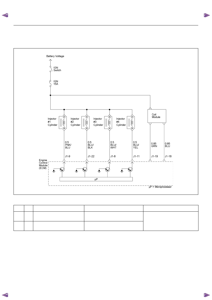
Circuit Description
The ignition control circuit provides a zero volt or a 5 volt
signal to the ignition control module. The normal circuit
voltage is zero volts. When the module receives the 5
volt signal from the ECM, it provides a ground path for
the B+ voltage supplied to the ignition primary coil.
When the ECM turns off the 5 volts to the module, the
module will remove the ground path of the ignition
primary coils; causing the magnetic field produces a
voltage in the secondary coils which fires the spark
plug.
The circuit between the ECM and the ignition control
module is monitored for an open circuit, short to voltage,
and short to ground. When the ECM detects a problem
in the ignition control circuit, it will set DTC P0351 or
P0352.
Diagnostic Aids
Check for the following conditions:
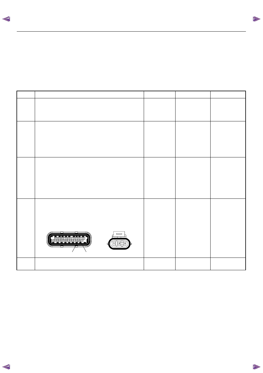
• Poor connection at the ECM - Inspect the harness
connectors for backed-out terminals, improper
Code
Type
DTC Name
DTC Setting Condition
Fail-Safe (Back Up)
P0351
A
Ignition 1 Control Circuit
#1 or #4cylinder ignition signals are not
detected consecutively.
No fail-safe function.
P0352
A
Ignition 2 Control Circuit
#2 or #3 cylinder ignition signals are not
detected consecutively.
ENGINE DRIVEABILITY AND EMISSIONS
6E–187
mating, broken locks, improperly formed or damaged
terminals, and poor terminal-to-wire connections.
• Damaged harness - Inspect the wiring harness for
damage; Open circuits, shorts to ground, or shorts to
Voltage. If the harness appears to be OK, observe
the Tech 2 display related to DTC P0351 or P0352
while moving the connector and wiring related to the
ignition system. A change in the display will indicate
the location of the fault.
Diagnostic Trouble Code (DTC) P0351 Ignition 1 Control Circuit
Diagnostic Trouble Code (DTC) P0352 Ignition 2 Control Circuit
Step
Action
Value(s)
Yes
No
1
Was the “On-Board Diagnostic (OBD) System Check”
performed?
—
Go to Step 2
Go to On Board
Diagnostic
(OBD) System
Check
2
1. Connect the Tech 2.
2. Review and record the failure information.
3. Select “F0: Read DTC Infor By Priority” in “F0:
Diagnostic Trouble Code”.
Is the DTC P0351 or P0352 stored as “Present
Failure”?
—
Go to Step 3
Refer to
Diagnostic Aids
and Go to Step
3
3
1. Using the Tech2, ignition “On” and engine “Off”.
2. Select “Clear DTC Information” with the Tech2 and
clear the DTC information.
3. Operate the vehicle and monitor the “F5: Failed
This Ignition” in “F2: DTC Information”.
Was the DTC P0351 or P0352 stored in this ignition
cycle?
—
Go to Step 4
Refer to
Diagnostic Aids
and Go to Step
4
4
Check for poor/faulty connection at the ignition coil
module or ECM connector. If a poor/faulty connection
is found, repair as necessary.
Was the problem found?
—
Verify repair
Go to Step 5
5
Visually check the ignition coil module.
Was the problem found?
—
Go to Step 12
Go to Step 6
19
18
E-60(J1)
E-18
6E–188
ENGINE DRIVEABILITY AND EMISSIONS
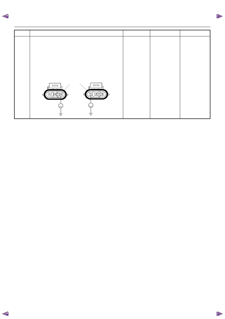
6
Using the DVM and check the ignition coil module
signal circuit for the affected coil.
1. Ignition “On”, engine “Off”.
2. Disconnect the ignition coil module connector.
3. Check the circuit for short to battery voltage circuit
for the affected coil.
Was the DVM indicated battery voltage?
—
Repair faulty
harness and
verify repair
Go to Step 7
Step
Action
Value(s)
Yes
No
E-18
1
11
1
Coil 2
V
E-18
3
33
3
Coil 1
V
ENGINE DRIVEABILITY AND EMISSIONS
6E–189
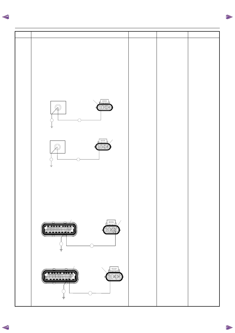
7
Using the DVM and check the ignition coil signal
circuit for the affected coil.
Breaker box is available:
1. Ignition “Off”, engine “Off”.
2. Install the breaker box as type A. (ECM
disconnected) Refer to 6E-88 page.
3. Disconnect the ignition coil module connector.
4. Check the circuit for open or short to ground circuit
for the affected coil.
Was the problem found?
Breaker box is not available:
1. Ignition “Off”, engine “Off”.
2. Disconnect the ignition coil module connector and
ECM connector.
3. Check the circuit for open or short to ground circuit
for the affected coil.
Was the problem found?
—
Repair faulty
harness and
verify repair
Go to Step 8
Step
Action
Value(s)
Yes
No
J1-18
Breaker Box
E-18
1
Coil 2
Ω
Ω
J1-19
Breaker Box
E-18
3
Coil 1
Ω
Ω
E-18
1
Coil 2
Ω
Ω
E-60(J1)
18
E-18
3
Coil 1
Ω
Ω
E-60(J1)
19
Нет комментариевНе стесняйтесь поделиться с нами вашим ценным мнением.
Текст