Isuzu KB P190. Manual — part 588

6E–182
ENGINE DRIVEABILITY AND EMISSIONS
6
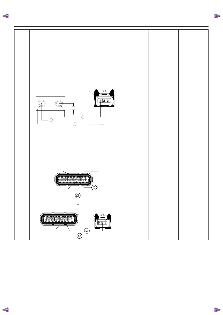
Using the DVM and check the CKP sensor circuit.
Breaker box is available:
1. Ignition “Off”, engine “Off”.
2. Install the breaker box as type A. (ECM
disconnected) Refer to 6E-88 page.
3. Check the resistance of the CKP sensor.
Was the DVM indicated specified value?
Breaker box is not available:
1. Ignition “Off”, engine “Off”.
2. Disconnect the ECM connector.
3. 3. Check the resistance of the CKP sensor.
Was the DVM indicated specified value?
Approximately
0.58k
Ω at
20°C
Go to Step 10
Go to Step 7
7
Using the DVM and check the CKP sensor circuit.
1. Ignition “Off”, engine “Off”.
2. Disconnect the CKP sensor connector.
3. Check the resistance of the CKP sensor.
Was the DVM indicated specified value?
Approximately
0.58k
Ω at
20°C
Go to Step 8
Go to Step 14
Step
Action
Value(s)
Yes
No
J1-6
J1-21
Ω
Breaker Box
6
21
E-60(J1)
CKP Sensor
3
1
2
2
1
Ω
ENGINE DRIVEABILITY AND EMISSIONS
6E–183
8
Using the DVM and check the CKP sensor circuit.
Breaker box is available:
1. Ignition “Off”, engine “Off”.
2. Install the breaker box as type A. (ECM
disconnected) Refer to 6E-88 page.
3. Disconnect the CKP sensor connector.
4. Check the circuit for open, short to sensor wire or
short to ground circuit.
Was the problem found?
Breaker box is not available:
1. Ignition “Off”, engine “Off”.
2. Disconnect the ECM connector.
3. Disconnect the CKP sensor connector.
4. Check the circuit for open, short to sensor wire or
short to ground circuit.
Was the problem found?
—
Repair faulty
harness and
verify repair
Go to Step 9
Step
Action
Value(s)
Yes
No
J1-6
J1-21
Breaker Box
E-59
Ω
Ω
Ω
2
22
2
1
11
1
Ω
6
E-60(J1)
21
E-59
E-60(J1)
6
21
2
1
6E–184
ENGINE DRIVEABILITY AND EMISSIONS
9
Using the DVM and check the CKP sensor circuit.
1. Ignition “On”, engine “Off”.
2. Disconnect the CKP sensor connector.
3. Check the circuit for short to power supply circuit.
If the DVM indicated out of specified value, repair
faulty harness and verify repair.
Is the action complete?
Less than 1V
Verify repair
—
10
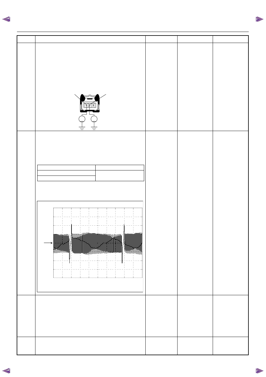
Using the DVM and check the CKP sensor signal.
1. Ignition “On”, engine “On”.
2. Measure the CKP output voltage at the sensor
and ECM.
Does the tester indicate standard voltage?
If a oscilloscope is available, monitor the CKP sensor
signal. Does the oscilloscope indicate correct wave
form?
Go to Step 13
Go to Step 11
11
Remove the CKP sensor from the flywheel housing
and visually check.
Check for the following conditions.
• Objects sticking the CKP sensor.
• Objects sticking the CKP sensor pulser.
If a problem is found, repair as necessary.
Was the problem found?
—
Verify repair
Go to Step 12
12
Check the CKP sensor shield wire for open or short
circuit.
Was the problem found?
—
Repair faulty
harness and
verify repair
Go to Step 13
Step
Action
Value(s)
Yes
No
V
V
E-59
2
1
Measurement Point
Voltage (V) (AC Range)
At CKP sensor terminal 1 & 2
Approx. 3.7V in engine idle
Approx. 7.8V at 2000rpm
At ECM E60 (J1) connector 21 & 6
Crankshaft Position (CKP) Sensor Reference Wave Form
0V
Measurement Terminal: J1-21(+) J1-6(-)
Measurement Scale: 10V/div 5ms/div
Measurement Condition: Approximately 2000rpm

ENGINE DRIVEABILITY AND EMISSIONS
6E–185
13
Check any accessory parts which may cause electric
interference or magnetic interference.
Was the problem found?
—
Remove the
accessory parts
and verify repair
Go to Step 14
14
Substitute a known good CKP sensor and recheck.
Was the problem solved?
—
Go to Step 15
Go to Step 16
15
Replace the CKP sensor.
Was the problem solved?
—
Verify repair
Go to Step 16
16
Is the ECM programmed with the latest software
release?
If not, download the latest software to the ECM using
the “SPS (Service Programming System)”.
Was the problem solved?
—
Verify repair
Go to Step 17
17
Replace the ECM.
Is the action complete?
IMPORTANT: The replacement ECM must be
programmed. Refer to section of the Service
Programming System (SPS) in this manual.
Following ECM programming, the immobilizer system
(if equipped) must be linked to the ECM. Refer to
section 11 “Immobilizer System-ECM replacement” for
the ECM/Immobilizer linking procedure.
—
Verify repair
—
Step
Action
Value(s)
Yes
No
Нет комментариевНе стесняйтесь поделиться с нами вашим ценным мнением.
Текст