Isuzu KB P190. Manual — part 1127
UNIT REPAIR (JR405E) 7A4-31
Reassembly steps
15PUMP18
1. O-ring (small)
Install new O-ring (small) to the oil pump housing.
16PUMP29
2. Outer rotor
3. Inner rotor
Install the outer rotor and the inner rotor to the oil pump
housing.
17PUMP42
NOTE:
The identification mark on the inner rotor must be facing
the inside of the oil pump housing.
18PUMP07
4. Oil pump cover
5. Oil pump housing
Install the oil pump cover to the oil pump housing.
Tighten the 8 bolts to the specified torque.
Torque: 9 N
⋅⋅⋅⋅m (0.9 kgf⋅⋅⋅⋅m/78 Ib⋅⋅⋅⋅in)
6. O-ring (large)
Install the O-ring (large) to the oil pump cover.
7. Seal ring
Install the 4 seal rings to the oil pump cover.

7A4-32 UNIT REPAIR (JR405E)
CLUTCH PACK (REVERSE AND
HIGH CLUTCH ASSEMBLY)
01R&H17
Legend
1. Reverse and high clutch drum
2. Seal ring (reverse clutch)
3. Lip seal (reverse clutch)
4. Reverse clutch piston
5. Seal ring (small, high clutch)
6. Seal ring (large, high clutch)
7. High clutch piston
8. Return spring
9. High clutch cover
10. Snap ring
11. Dish plate (high clutch)
12. Driven plate (5, high clutch)
13. Drive plate (5, high clutch)
14. Retaining plate (high clutch)
15. Snap ring (high clutch)
16. Dish plate (reverse clutch)
17. Driven plate (2, reverse clutch)
18. Drive plate (2, reverse clutch)
19. Retaining plate (reverse clutch)
20. Snap ring (reverse clutch)
02R&H18
Disassembly steps
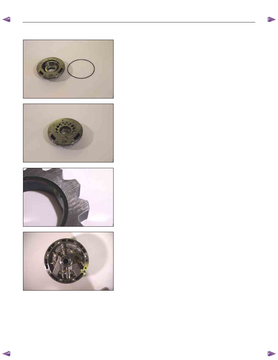
1. Snap ring
Remove the reverse clutch snap ring.
UNIT REPAIR (JR405E) 7A4-33
03R&H21
2. Retaining plate, drive plates, driven plates and dish
plate
Remove the reverse clutch retaining plate, the 2 drive
plates, the 2 driven plates, and the dish plate.
04R&H22
3. Snap ring
Remove the high clutch snap ring.
05R&H25
4. Retaining plate, drive plates, driven plates and dish
plate
Remove the high clutch retaining plate, the 5 drive plates,
the 5 driven plates, and the dish plate.
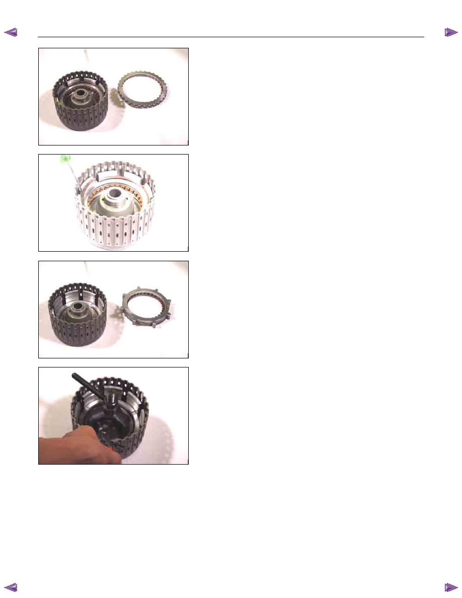
07R&H28
5. Snap ring
6. High clutch cover
7. Return spring
• Install the spring compressor to the reverse and high
clutch drum.
Spring compressor: 5-8840-2767-0
• Carefully press the high clutch cover down.
Take care not to damage the return spring.
• Remove the snap ring.
• Remove the high clutch cover and the return spring.
7A4-34 UNIT REPAIR (JR405E)
08R&H36
8. High clutch piston
9. Reverse clutch piston
• Install the reverse and high clutch drum to the oil pump.
• Force compressed air into the oil pump oil channels.
• Remove the high clutch piston and the reverse clutch
piston.
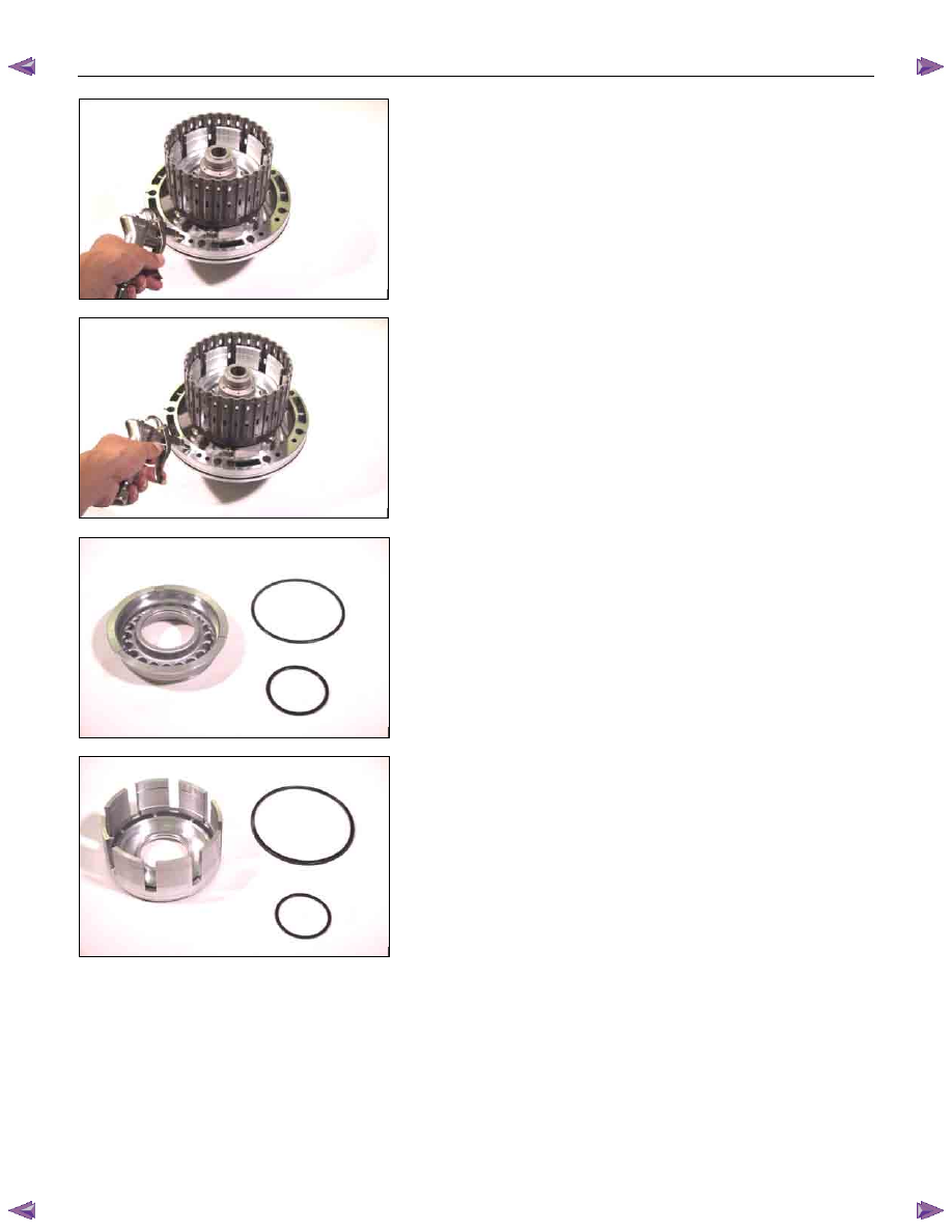
09R&H37
12R&H39
10.Seal ring (high clutch)
Remove the 2 seal rings from the high clutch piston.
13R&H38
11.Seal ring (reverse clutch)
Remove the 2 seal rings from the reverse clutch piston.
Inspection
Drive plates
• Measure the drive plate facing thickness at 3 points.
• Calculate the average value.
If the average value is less than the specified limit, the
drive plate must be replaced.
Drive plate facing thickness:
Standard – 2.0 mm (0.079 in)
Limit – 1.8 mm (0.071 in)
Нет комментариевНе стесняйтесь поделиться с нами вашим ценным мнением.
Текст