Isuzu KB P190. Manual — part 1128
UNIT REPAIR (JR405E) 7A4-35
Return springs
• Check the number of effective return spring coils.
If the number is less than the specified minimum, the
return spring must be replaced.
Effective return spring coils (standard): 10.2
• Measure the return spring outside diameter, free length,
and linear diameter.
If any of the measured values exceed the specified limit,
the return spring must be replaced.
Return spring measurements (standard):
Outside diameter – 8.0 mm (0.315 in)
Free length – 27.1 mm (1.067 in)
Linear diameter – 1.1 mm (0.043 in)
10R&H40
Reverse clutch piston
• Apply compressed air (390 kPa/4.0 kgf/cm
2
/57 psi) to
the reverse clutch piston from the outside to the inside.
The flow of air should be blocked.
11R&H44
• Apply compressed air (390 kPa/4.0 kgf/cm
2
/57 psi) to
the reverse clutch piston from inside to the outside.
The flow of air should be unrestricted.
12R&H39
Reassembly steps
Coat the parts with ATF before installing them.
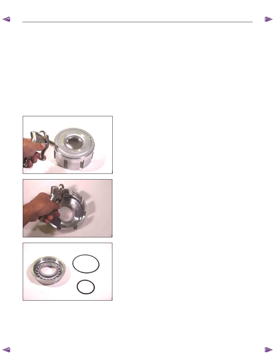
1. Seal ring (high clutch)
Install new seal rings to the high clutch piston.
7A4-36 UNIT REPAIR (JR405E)
13R&H38
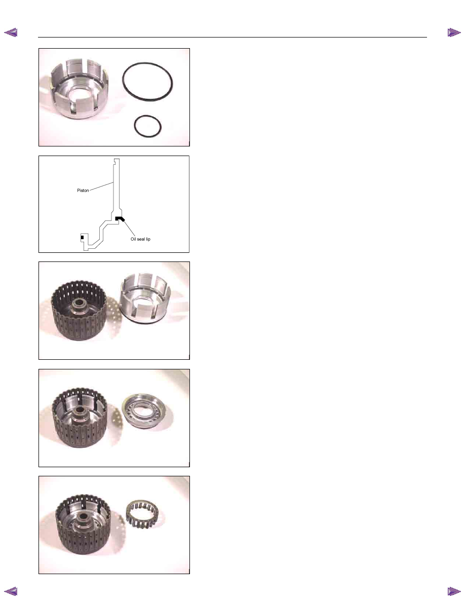
2. Seal ring (reverse clutch)
Install new seal rings to the reverse clutch piston.
RTW47ASH000601
As shown in a figure, oil seal lip is attached.
14R&H32
3. Reverse clutch piston
Install the reverse clutch piston to the reverse and high
clutch drum.
15R&H31
4. High clutch piston
Install the high clutch piston to the reverse clutch piston.
16R&H33
5. Return spring
Install the return spring to the high clutch piston.
UNIT REPAIR (JR405E) 7A4-37
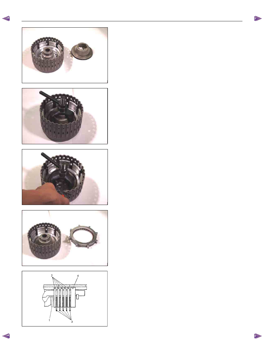
17R&H30
6. High clutch cover
• Carefully center the high clutch cover and install it.
NOTE:
If the clutch cover is not centered, the cover outside seal
gum will be forced into the piston area where it will be
damaged.
18R&H27
7. Snap ring
• Install the spring compressor to the reverse and high
clutch drum.
• Use the spring compressor to carefully force the high
clutch cover down.
Spring compressor: 5-8840-2767-0
NOTE:
To avoid damage to the return springs, use only as much
force as is required to press the high clutch cover into
place.
19R&H28
• Install the new snap ring to the reverse and high clutch
drum.
20R&H25
8. Dish plate, drive plates, driven plates, and retaining
plate
Install the high clutch dish plate (1), the 5 driven plates (2),
the 5 drive plates (3), and retaining plate (4).
RTW47ASH000501
9. Snap ring
Install the snap ring.
NOTE:
Ensure the attachment direction of dish plate (1) is correct.
7A4-38 UNIT REPAIR (JR405E)
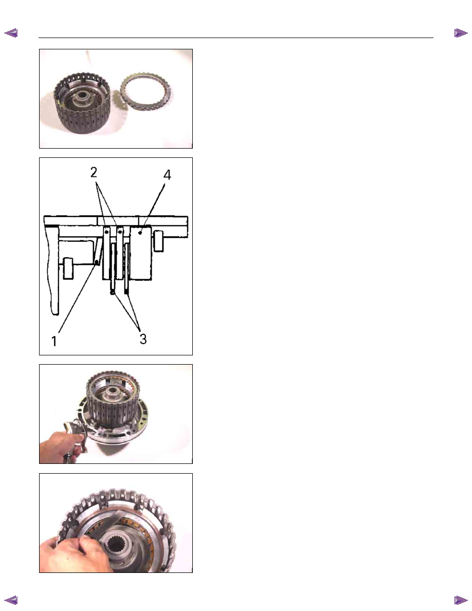
21R&H21
10.Dish plate, drive plates, driven plates, and retaining
plate
Install the reverse clutch dish plate (1) the 2 driven plates
(2), the 2 drive plates (3), and retaining plate (4).
248L300003
11.Snap ring
Install the snap ring.
NOTE:
Ensure the attachment direction of dish plate (1) is correct.
22R&H35
• Install the reverse and high clutch drum to the oil pump
assembly.
• Force compressed air (390 kPa/4.0 kgf/cm
2
/57 psi)
through the oil pump oil passages to check high clutch
operation.
If the clutch does not operate, the seal ring may be
damaged or the parts may have been installed in the
wrong order.
23CLEAR02
• Measure the clearance between the high clutch retaining
plate and the snap ring.
If the clearance is outside the specified range, replace
the existing retaining plate with a new plate of the proper
size (thickness).
High clutch retaining plate and snap ring clearance
(A): 1.2~1.6 mm (0.047~0.063 in)
Available high clutch retaining plate thicknesses
4.6 mm (0.181 in)
4.8 mm (0.189 in)
Нет комментариевНе стесняйтесь поделиться с нами вашим ценным мнением.
Текст