Isuzu KB P190. Manual — part 1338
8A-414 ELECTRICAL-BODY AND CHASSIS
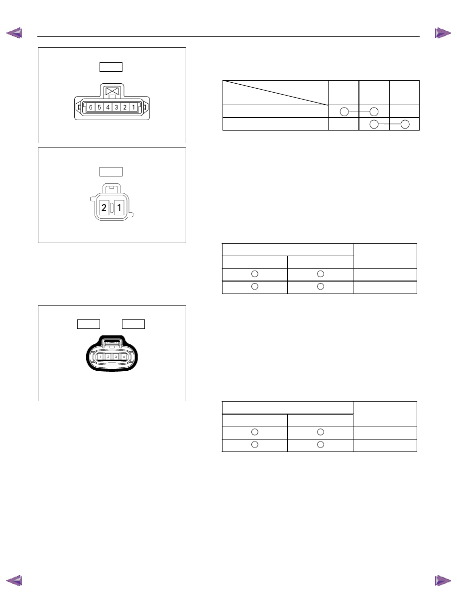
Switch side
D4
Driver’s Side Door Lock Switch
1. Switch Side Connector Circuit
Check continuity between the switch connector terminals
Terminal No.
SW position
1 2 3
Lock
Unlock
Actuator side
D9
Front Passenger’s Side Door Lock Actuator
1. Actuator Side Connector Circuit
Apply the battery voltage to the actuator connector
terminals to check the operation.
When the door lock actuator is checked on the vehicle and
there is no continuity, and when the door lock actuator itself
is checked and no trouble is found, check the circuit
between the door lock actuator and the driver seat side
power window & door lock switch for any failure.
Connecting terminals
1 2
+
-
Lock
-
+
Unlock
Operation
Door lock actuator Rear – RH/LH
Harness side
D14
D18
Rear Door Lock Actuator -LH & RH
1. Actuator Side Connector Circuit
Apply the battery voltage to the actuator connector
terminals to check the operation.
When the door lock actuator is checked on the vehicle and
there is no continuity, and when the door lock actuator itself
is checked and no trouble is found, check the circuit
between the door lock actuator and the driver seat side
power window & door lock switch for any failure.
Connecting terminals
1 2
+
-
Lock
-
+
Unlock
Operation
ELECTRICAL-BODY AND CHASSIS 8A-415
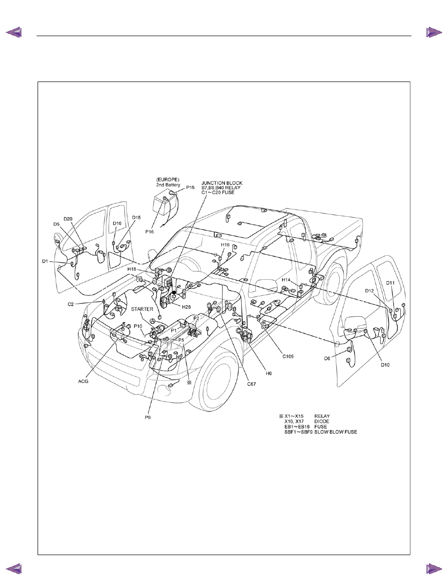
POWER WINDOW
PARTS LOCATION (RHD)
RTW78AXF039501
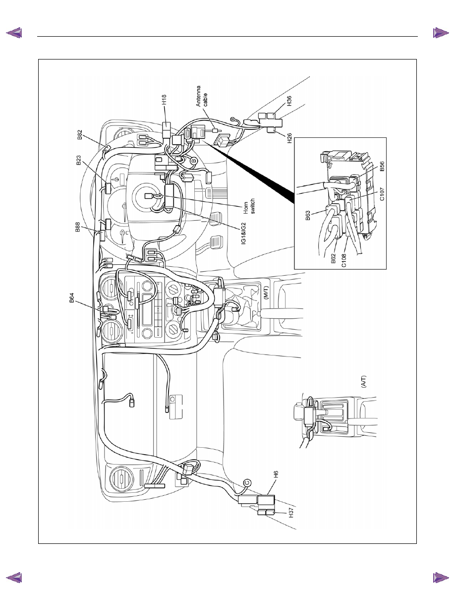
8A-416 ELECTRICAL-BODY AND CHASSIS
PARTS LOCATION (RHD)
RTW78AXF045701
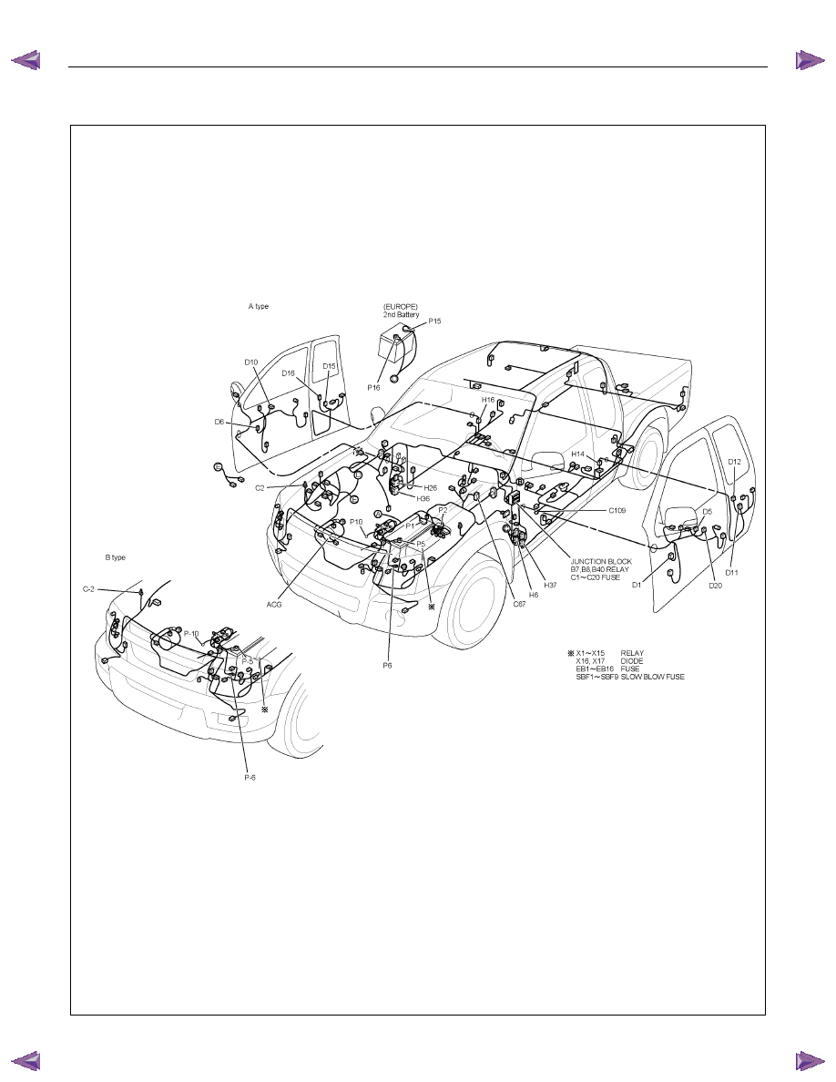
ELECTRICAL-BODY AND CHASSIS 8A-417
PARTS LOCATION (LHD)
RTW78AXF039601
Нет комментариевНе стесняйтесь поделиться с нами вашим ценным мнением.
Текст